Tapered Tube Enclosures for loudspeakers
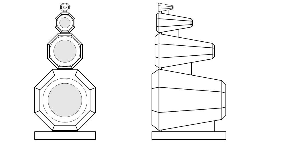
VCLLabs has done research on the use of tapered tubes in loudspeaker design. Compared to traditional box-style loudspeakers, the front baffle area around the transducers is significantly smaller in a tapered tube design. This configuration is expected to produce a different sound radiation pattern, with greater backward radiation. Additionally, the directivity and power response of a loudspeaker utilizing a tube cabinet are expected to differ from those of conventional designs.
To better understand the behavior of tapered tubes, we decided to create two loudspeaker designs using the same drivers but with different cabinet types: one featuring tapered tubes and the other a traditional box cabinet. By simulating both designs and comparing their responses in terms of on-axis and off-axis SPL, power output, and directivity index, we aim to gain deeper insights into the performance characteristics of the tube-based design.
The loudspeakers are designed as 4-way systems. Simulation results later confirmed that the optimal performance for a tapered tube speaker is achieved with a 4-way configuration, which is why this design was selected.
The transducers used in the design are as follows:
- Tweeter: Scanspeak D2004-662200
- Midrange: Bliesma M74B-6
- Midwoofer: Audio Technology 23 I 52 17 06 SDKA 03
- Woofer: Audio Technology 12D77
The sizes of the transducers were carefully selected to ensure optimal performance within their respective frequency ranges, enabling the system to effectively cover the entire audible spectrum from 20 Hz to 20,000 Hz.
The research was conducted using simulations in the Leap EnclosureShop speaker design tool. No acoustic measurements have been performed to verify these simulations so far. There are plans to create prototype tubes to evaluate the simulations.
Contents
- Cabinets used for this study
- Tweeter
- Midrange
- Midwoofer
- Woofer
- All Transducers
- Crossover filter
- Conclusion
Cabinets used for this study
Tapered tube 4-way loudspeaker and Box-type 4-way loudspeaker
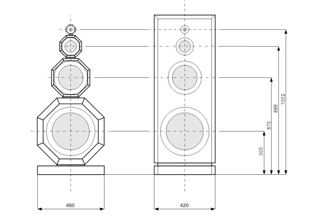
It can be observed that the box-type speaker has significantly more baffle surrounding the transducer’s moving piston. Reflections of the radiated sound on the baffle can interfere with the direct sound from the piston. In the simulations, the tube cabinet shape required some optimization to achieve the best-performing radiation results. The transition from the front to the back side of the cabinet, as well as the shape of the tube at the backside, play a crucial role in determining the behavior. The primary focus of this study is to examine how system parameters on-axis and off-axis SPL, power, and directivity differ and influence sound performance.
The tube cabinets for the various speaker transducers are designed with identical shape and dimensional ratios to ensure consistent sound radiation across each transducer’s operating frequency range. The only exception is the woofer tube, where the depth at the rear is reduced to enhance practical usability.
Key parameters to consider in this study are the baffle step frequency and the transducer’s radiation beamwidth.
For a transducer mounted in a cabinet, the transition from half-space to full-space radiation – commonly referred to as the “baffle step” – starts at the frequency where the cabinet width becomes equal to the wavelength of the sound.
The radiation beamwidth of a transducer mounted on an infinite baffle is determined by the diameter of its moving piston. The radiation beamwidth marks the frequency at which the sound wavelength is equal to the circumference of the circular transducer’s moving piston. It is also commonly regarded as the point where the transducer transitions from omnidirectional to directional radiation on an infinite baffle.
Simulations indicate that, at frequencies above the baffle step frequency, and for transducers with sufficient radiation bandwidth at these frequencies, there is a non-uniform off-axis radiation pattern. This behavior impacts both the power and directivity responses. Further insights can be gained from the simulation results.
Tweeter
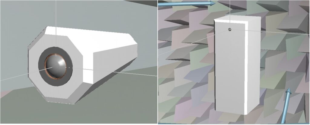
Scanspeak D2004-602200 in a tapered tube with dimensions W x H x D = 69 x 69 x 120 mm and octagonal front panel with radius 37 mm. The calculated bafflestep frequency is 5000 Hz and the calculated tweeter radiation beamwidth is 4713 Hz.
Scanspeak D2004-602200 in a box W x H x D = 42 x 110 x 46 cm.
The calculated bafflestep frequency is 821 Hz and the calculated tweeter radiation beamwidth is 4713 Hz.
Simulation in Leap – Tweeter in tube and tweeter in box
SPL on axis (red) and SPL on infinite baffle (pink) at 3m, 2.83 Vrms in full space
tube (left), box (right)

For the tube, the baffle step frequency occurs at 4 kHz compared to 800 Hz for the box, which results in a lower SPL below 4 kHz for the tube.
SPL on axis and horizontal off axis 15 30 45 60 75 90 degrees at 3m, 2.83 Vrms in full space
tube (left), box (right)

The tube shows significantly more uniform off-axis radiation behavior around the baffle step frequency of 5 kHz and higher. In contrast, in the box-type design, the reflected sound from the surrounding baffle interferes with the direct sound produced by the transducer’s moving piston. This interaction affects the radiation above the baffle step frequency, resulting in less uniformity.
Horizontal polar diagram 1.28 – 2.56 – 3.84 – 5.12 – 6.40 – 12.80 kHz at 3m in full space
tube (left), box (right)

In these horizontal polar plots, it is observed that relatively more power is radiated to the backside when using a tube. For the box-type, the radiation is omnidirectional and fairly uniform up to 75 degrees off-axis. However, this uniformity is achieved through additional interfering baffle reflections, which is a key difference. Practical listening tests are needed to compare the performance of both designs in the tweeter’s operating frequency range.
SPL on axis (black) and the power (red) at 3m, 2.83 Vrms in full space
tube (left), box (right)

In the box-type design, the power response is flatter in the tweeter’s operating frequency range, but it is achieved through interfering baffle reflections.
Directivity Index at 3m in full space (red) and on infinite baffle (yellow)
tube (left), box (right)

Also in the comparing directivity index curves, it can be observed a more extended flat directional behavior for the box-type design, caused by the larger surrounding front baffle.
Midrange
Bliesma M74B-6 in a tapered tube enclosure with dimensions W x H x D = 150 x 150 x 260 mm and octagonal front panel with radius 81 mm. The calculated bafflestep frequency is 2300 Hz and the calculated midrange radiation beamwidth is 1373 Hz.
Bliesma M74B-6 in a box W x H x D = 42 x 110 x 46 cm.
The calculated bafflestep frequency is 821 Hz and the calculated midrange radiation beamwidth is 1373 Hz.
Simulation in Leap – Midrange in tube and midrange in box

SPL on axis (green) and SPL on infinite baffle (pink) at 3m, 2.83 Vrms in full space
tube (left), box (right)

SPL on axis and horizontal off axis 15 30 45 60 75 90 degrees at 3m, 2.83 Vrms in full space
tube (left), box (right)

For the box-type speaker, the off-axis response is less uniform. At 1.2 kHz, there is a dip in the on-axis SPL, caused by reflections and diffractions from the front baffle. The baffle step frequency at 820 Hz and the midrange radiation beamwidth of 1373 Hz causes this non-uniform behavior.
Polar diagram 0.64 – 1.28 – 2.56 – 3.84 – 5.12 kHz at 3m in full space
tube (left), box (right)

It can be observed that the box-type speaker becomes much more omnidirectional at 1.2 kHz than the tube speaker, and the radiation towards the backside is relatively lower compared to the tube.
SPL on axis (black) and the power (green) at 3m, 2.83 Vrms in full space
tube (left), box (right)

Directivity Index at 3m in full space and on infinite baffle (yellow)
tube (left), box (right)

For the box-type speaker, the directivity index shows a dip at 1.2 kHz, caused by interference with baffle reflections. This means the DI is not flat in the midrange operating frequency band. As a result, equalizing the on-axis SPL response to be flat will not produce a flat power response. Some optimization is required. To improve this behavior, options include placing the midrange driver asymmetrically on the front baffle, choosing a curved front baffle or applying a waveguide, which can reduce front baffle reflections and interactions with the direct sound from the moving piston.
Midwoofer
Audio Technology C-Quenze 23 I 52 17 06 SDKA 03 in a tapered tube enclosure with dimensions W x H x D = 264 x 264 x 458 mm and octagonal front panel with radius 142 mm. The calculated bafflestep frequency is 1306 Hz and the calculated midwoofer radiation beamwidth is 646 Hz.
Audio Technology C-Quenze 23 I 52 17 06 SDKA 03 in a box W x H x D = 42 x 110 x 46 cm.
The calculated bafflestep frequency is 821 Hz and the calculated midwoofer radiation beamwidth is 646 Hz
Simulation in Leap – Midwoofer in tube and midwoofer in box

SPL on axis (brown) and SPL on infinite baffle (pink) at 3m, 2.83 Vrms in full space
tube (left), box (right)

SPL on axis and off axis 15 30 45 60 75 90 degrees at 3m, 2.83 Vrms in full space
tube (left), box (right)

As the midwoofer radiation beamwidth is lower than the baffle step frequency for both the tube and the box-type speaker, the off axis response shows a good behavior for both speaker types. The box-type speaker off axis response is less uniform at 1200 Hz as the baffle step frequency of the box-type speaker is lower, the surounding front baffle is larger.
Polar diagram 160 – 320 – 640 – 1280 – 2560 Hz Hz at 3m in full space
tube (left), box (right)

The tube speaker shows more backwards radiation. Both the tube and box-type speakers show a similar uniform behavior on the front side.
SPL on axis (black) and the power (brown) at 3m, 2.83 Vrms in full space

Directivity Index at 3m in full space and on infinite baffle (yellow)
tube (left), box (right)

Woofer
Audio Technology 12 D 77 25 10 KAP in a tapered tube enclosure with dimensions W x H x D = 460 x 460 x 550 mm and octagonal front panel with radius 249 mm. The calculated bafflestep frequency is 750 Hz and the calculated woofer radiation beamwidth is 429 Hz
Audio Technology 12 D 77 25 10 KAP in a box W x H x D = 42 x 110 x 46 cm. The calculated bafflestep frequency is 821 Hz and the calculated midwoofer radiation beamwidth is 429 Hz
Since the enclosure width is nearly identical for both types of speakers, the baffle step frequency is the same. The woofer’s radiation beamwidth is lower than the baffle step frequency, ensuring a uniform off-axis response for frequencies above the baffle step frequency.
Simulation in Leap – Woofer in tube and midwoofer in box

SPL on axis (blue) and SPL on infinite baffle (pink) at 3m, 2.83 Vrms in full space
tube (left), box (right)

SPL on axis and horizontal off axis 15 30 45 60 75 90 degrees at 3m, 2.83 Vrms in full space
tube (left), box (right)

Polar diagram 80 – 160 – 320 – 640 – 1280 Hz at 3m in full space
tube (left), box (right)

SPL on axis (black) and the power (blue) at 3m, 2.83 Vrms in full space
tube (left), box (right)

Directivity Index at 3m in full space and on infinite baffle (yellow)
tube (left), box (right)

The DI curves for both cabinet types are similar and show a monotonic increase.
All transducers
Directivity Index at 3m in full space of woofer (blue), midwoofer (brown), midrange (green)
and tweeter (red)
tube (left), box (right)

Displaying the DI curves of the four transducers in a single plot provides deeper insight into the crossover design of a 4-way speaker for both box and tube enclosure types.
For the tube speaker, the DI curves exhibit a monotonic increase, primarily due to transducer beaming at higher frequencies. The front baffles surrounding the woofer, midwoofer, and midrange drivers have minimal impact. However, for the tweeter in the tube enclosure, the DI decreases above 5 kHz. This decrease is caused by reflections from the tweeter’s surrounding baffle at these frequencies.
In box-aligned speakers, the DI curves flatten above the baffle step frequency of the respective tubes. As mentioned, non-uniform off-axis radiation becomes apparent in this frequency range.
When designing a loudspeaker with four transducers, setting the crossover frequencies at 140 Hz, 650 Hz, and 3000 Hz optimizes the overall directivity index (DI) for the combined response. These crossover points ensure smooth transitions between drivers, resulting in an optimal performance.
Back to top of page
Crossover filter
To gain a clear understanding of the behavior of tube and box-type cabinets in a complete 4-way speaker system, a crossover filter is designed for both enclosure types. Simulations are done to analyze on- and off-axis SPL, power, and directivity, and the results are compared.
Crossover filter targets LR4 at 140, 650 and 3000 Hz
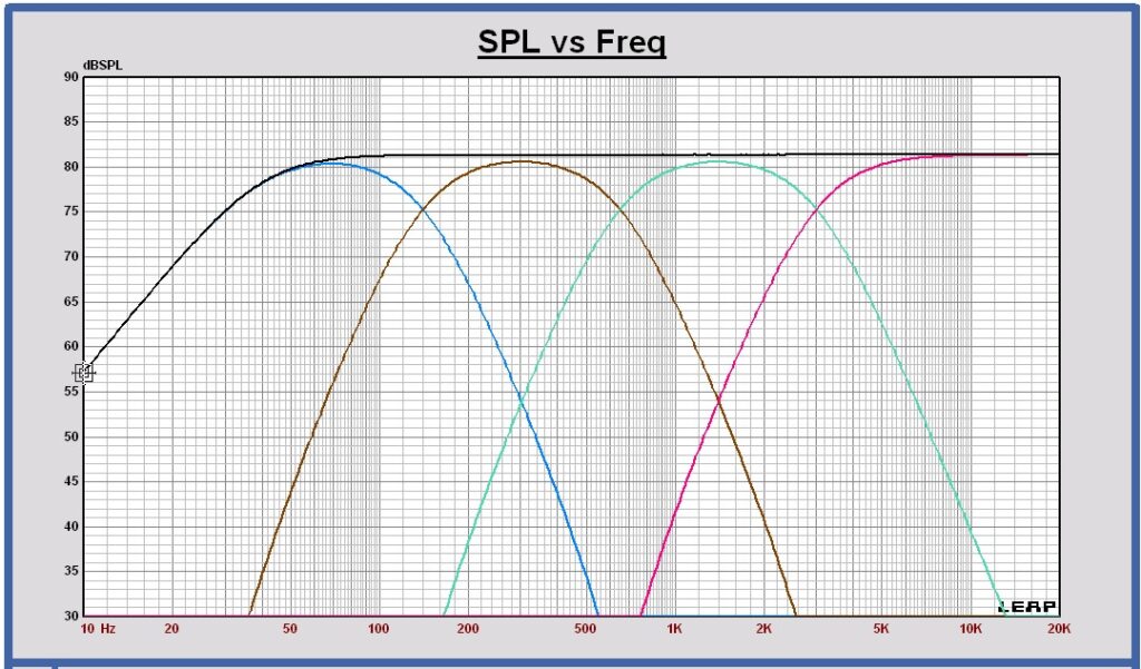
SPL on axis of the filtered drivers and the sum at 1m, 2.83 Vrms in full space
tube (left), box (right)

SPL horizontal off axis of the sum at 0 , 30 and 60 degrees at 3m, 2.83 Vrms
tube (left), box (right)

For the box-type speaker, non-uniform behavior can be observed in the off-axis sum response above the baffle step frequency, around 1200 Hz. In contrast, the tube speaker exhibits much more uniform off-axis behavior.
Power response of the filtered drivers and the sum in free space at 3m, 2.83 Vrms in full space
tube (left), box (right)

The two speaker types show different power sum responses as a function of frequency. For the tube speaker, the power response decreases more monotonically to higher frequencies and the power in the high-frequency range becomes lower. This characteristic is expected to influence the overall sound performance.
The box-type speaker shows a local power increase around 1200 Hz, which is caused by the midrange driver’s interaction with the front baffle.
Directivity Index in free space of the filtered drivers and the sum
tube (left), box (right)

A similar observation to that seen in the power response can also be made in the DI curve of the sum.
Voltage transfers
tube (left), box (right)

Voltage transfers compared
tube in dark color, box in ligth color
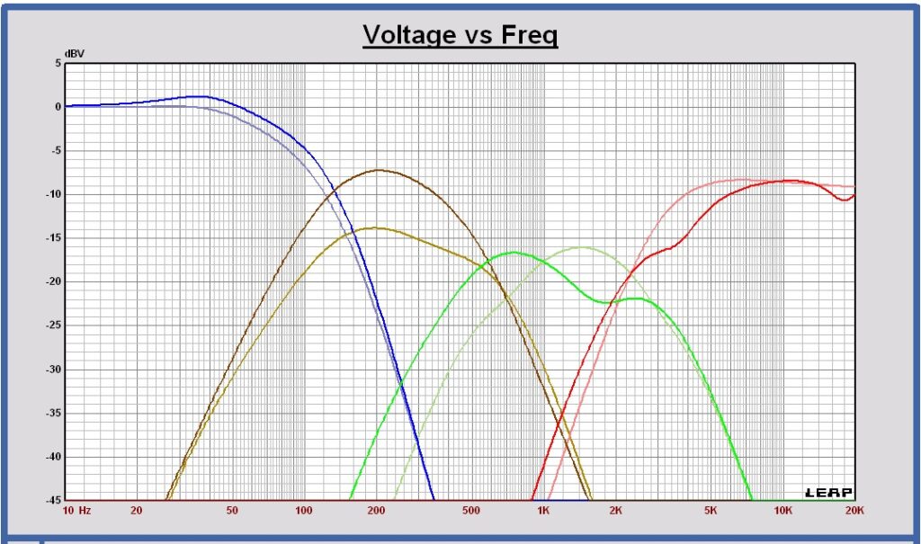
Tube speakers are smaller, which raises the baffle step frequency. This results in more omnidirectional radiation extending to lower frequencies compared to their box-type versions. As a consequence, more voltage is required to achieve a flat on-axis SPL at these frequencies.
Above the baffle step frequency, tube speakers require less power, as box-type speakers exhibit more omnidirectional radiation in this frequency range and therefore need more voltage to maintain a flat SPL sum response.
Conclusion
A study has been done to evaluate the use of tapered tube enclosures for loudspeakers as an alternative to the conventional box-type enclosures. Simulations of both enclosure types were performed using Leap EnclosureShop, yielding several notable conclusions.
Tube Enclosures
Using a tube enclosure allows for a smaller front baffle surrounding the transducer. This design shifts the baffle step frequency higher, reducing the radiated power of the transducer at this frequency and above. As a consequenze, front baffle reflections above the baffle step frequency are minimized, resulting in less interference with the direct sound. Consequently, the polar response becomes more uniform.
Box-Type Enclosures
In box-type enclosures, drivers are typically mounted on a single common front baffle, which results in a larger surrounding baffle for each transducer. This design lowers the baffle step frequency, leading to increased radiated power of the transducer around this frequency and above. Front baffle reflections become larger and interfere with the direct sound and affect uniformity in off-axis radiation.
Some solutions to improve these effects can be considered. Curved front baffles, waveguides for the smaller transducers and an assymmetric placement on the front baffle are some possible options.
Further Evaluation
To date, the simulation results of this study have not been verified with practical acoustical measurements. Moreover, the claimed benefits of tube enclosures, including more uniform off-axis behavior and a different distribution of radiated power (with more power directed backward), require further practical evaluation to confirm their validity.
