ASP active filter using opamp filter blocks
For an ASP filter design, a minimum phase filter design with active generic filter blocks can be used to start. The acoustic centers are added to the driver models and the delay caused by the different acoustic centers of the drivers are compensated. The generic filter blocks will be transformed to opamp filter blocks.
Contents
- VCLLabs opamp filter blocks
- Active filter design with generic filter blocks with driver delay compensation
- ASP filter schematic with analog opamp filter blocks
VCLLabs opamp filter blocks
To realize an ASP crossover filter, VCLLabs has designed a set of opamp filter blocks to transform most of the generic filter blocks that are needed to make an ASP filter.
The blocks are:
- LP1 Low Pass first order unity gain
- HP1 High Pass first order unity gain
- AP1 All Pass first order unity gain
- LP2 Low Pass second order unity gain
- HP2 High Pass second order unity gain
- AP2 All Pass second order unity gain
- BP1 First order bandpass filter – A dB gain
- BR1 fz > fh Band reject filter first order – fz higher fp
- BR1 fz < fh Band reject filter first order – fz lower fp
- LEQ boost Low Frequency Equalization
- LEQ cut Low Frequency Equalization
- HEQ boost High frequency Equalization
- HEQ cut High frequency Equalization
- BEQ boost Parametric Band Equalizer second order
- BEQ cut Parametric Band Equalizer second order
For all these generic filter blocks, library blocks are created in VituixCAD. These blocks are added to the VituixCAD Block Library list since version 2.0.108.1 (2023-09-03) and later.
Active filter design with generic filter blocks with driver delay compensation
Start (VituixCAD).
To start, an existing active filter minimum phase design with generic filter blocks can be used, or a new one can be designed like described in Tech Page 13 – VCLLabs
Important, select (VituixCAD -> Options-> set the “Save chart overlay to project” to on.
Important, to make an ASP crossover design, select (VituixCAD -> Options-> Frequency Responses) and set the DSP system to “Analog”.
For a minimum phase design (no acoustic center differences), it is possible to make a filter with the phases aligned for all filtered drivers.
Acoustic centers setting
For the loudspeaker design example VCL EM2, the woofer acoustic center is 40 mm behind the tweeter acoustic center and the midrange is 20 mm behind.
Select each driver with the mouse and adapt the z coordinates.
Z coordinate driver #1 = 40 mm
Z coordinate driver #2 = 20 mm
Z coordinate driver #3 = 0 mm
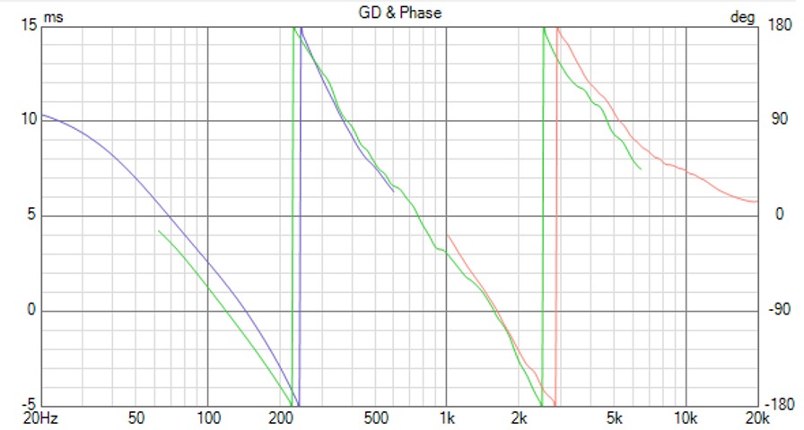
Looking now to the phase plot, there can be observed that the midrange phase (green curve) is lagging to the tweeter phase (red curve). The woofer phase (blue curve) also shows some extra delay, but no compensation is needed as the phase shift is minimum (in this case).

Compensation of driver delays
Some compensation for the midrange delay can be realized by adding an all pass filter to the tweeter filter.
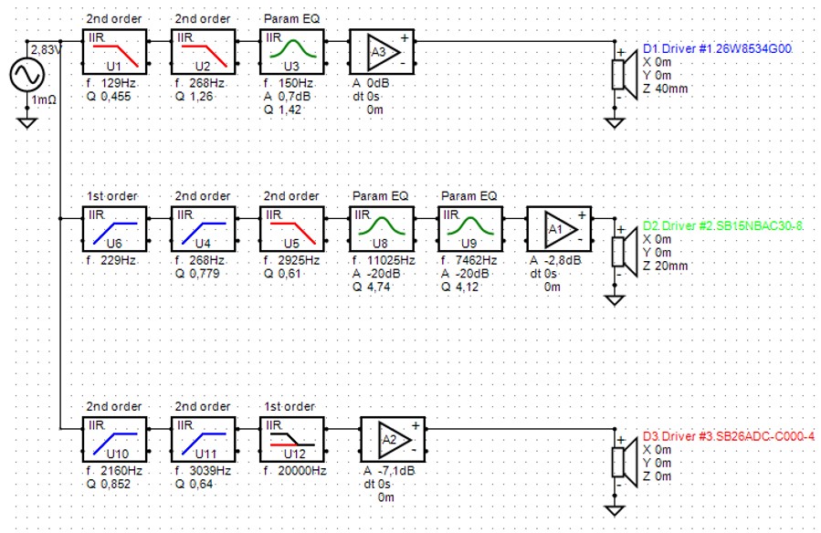
A first order all pass filter at 20 kHz is added to the tweeter filter. The generic all pass filter block can be chosen in the menu. Selecting the block in the schematic, first order and frequency at 20 kHz can be chosen in the pop – up window.

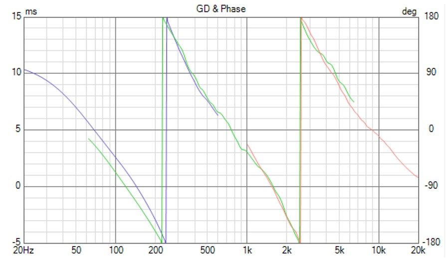
The midrange and tweeter phase are aligned again by adding the all pass filter to the tweeter filter.

ASP filter schematic with analog opamp filter blocks
The following generic filter blocks are needed:
Woofer filter
LP2 129 Hz Q = 0.456
LP2 267 Hz Q = 1.26
BEQ 150 Hz Q = 1.42 A = 0.7 dB
gain block 0 dB
Midrange filter
HP1 229 Hz
HP2 268 Hz Q = 0.779
LP2 2925 Hz Q = 0.61
BEQ 11025 Hz Q = 4.74 A = -20 dB
BEQ 7462 Hz Q = 4.12 A = -20 dB
gain block -2.8 dB
Tweeter filter
HP2 2160 Hz Q = 0.852
HP2 3039 Hz Q = 0.64
AP1 20000 Hz
gain block -7.1 dB
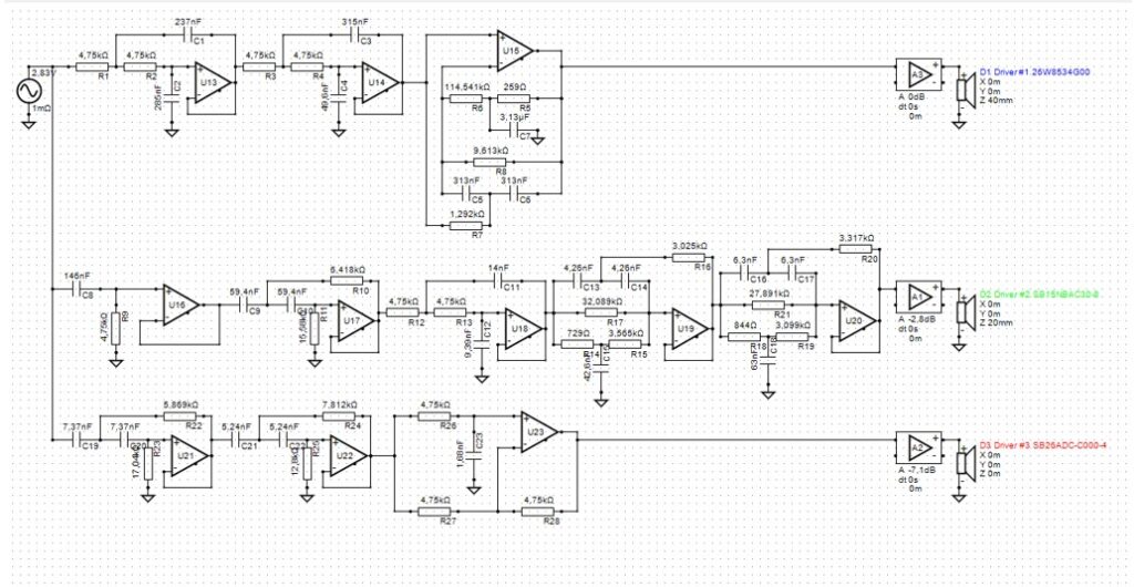
Below the schematic in Vituix using the VCLLabs opamp filter blocks.

All the responses with this schematic with opamp blocks are the same as the schematic with the generic blocks.

