April 2024,
High slope Crossover Filters for Loudspeakers
New 12th order all-pole filter AP12
Contents
- General
- Linkwitz Riley 4th and 8th order filters
- Elliptical 3rd and 5th order filters
- New 12th order AP12 All Pole filter
- Some considerations about high slope filtering
- Listening tests
– Crossover designs used for listening tests
– Listening experiences - Realization of the AP12 crossover filter
General
Since many years VCLLabs has done a lot of investigation on loudspeaker crossover design to try to find the best performing ones. We designed elliptical filters using our own filter targets. The EL3 third order elliptical version is performing very well, very lively and expressive with a high level of life experience. The EL5 fifth order elliptical version is performing even better than the EL3, more pure and powerful. EL5 is the best performing filter till now and we use it in many loudspeaker designs. Very remarkable in all these designs, the differences between EL3, EL5, LR4 and other classical filter types are very consistent across the different designs.
Recently, we created the new AP12 filter, which is a 12th order all-pole filter with also outstanding listening results.
Linkwitz-Riley 4th and 8th order
These are even order filters. They consist of one or more cascaded second order filter sections. Very popular are the second order LR2 and the fourth order LR4 filters.
SPL
Voltage level at the crossover frequency is – 6dB. The SPL sum is flat around the crossover point.
Phase
Low pass and high pass sections are phase aligned. The sections are in phase. The group delay has a small boost around the crossover frequency.
Power
For frequencies where the distance between the transducer centers becomes close to the wavelength of the sound, there is a power dip at the crossover frequency.
Polar
Very characteristic for these filters is a symmetric vertical polar diagram around the on axis at the crossover frequency, if the distance between the transducer centers becomes close to the wavelength of the sound. The SPL is maximum on axis, there is no SPL boost off axis.
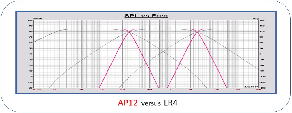
Example LR4 and LR8 targets
Targets 3 way LR4 and LR 8 at 250 – 2500 Hz @ F3 = 25 Hz B3 highpass

LR4 in grey and LR8 in red
Groupdelay LR4 and LR8
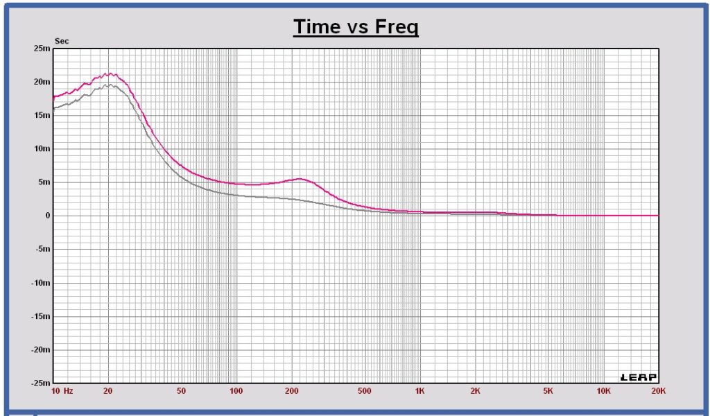
LR4 in grey and LR8 in red
Elliptical 3rd and 5th order filters
VCLLabs has designed a third order EL3 and a fifth order EL5 version. They are designed for the sum response to have minimal ripple and the phase as best aligned as possible.
SPL
Voltage level at the crossover frequency is – 6dB.
For the odd order VCLLabs versions EL3 and EL5 the SPL sum has a small ripple of +/- 0.25 dB around the crossover point.
Phase
For the odd order VCLLabs versions EL3 and EL5, there is a phase difference of about 10 degrees around the crossover point.
Power
For frequencies where the distance between the transducer centers becomes close to the wavelength of the sound, there is a small power dip at the crossover frequency.
Polar
For these filters the vertical polar diagram at the crossover frequency is almost symmetric, if the distance between the transducer centers becomes close to the wavelength of the sound.
Example EL3 and EL5 targets
Targets 3 way EL3 at 250 – 2500 Hz @ F3 = 25 Hz B3 highpass
Targets 3 way EL5 at 250 – 2500 Hz @ F3 = 25 Hz B3 highpass
Targets EL5 and EL3 for woofer and midrange compared — scale 10 dB/div

EL3 in grey and EL5 in blue and green
The outband reduction of the EL3 is 30 dB, and 55 dB for the EL5.
Groupdelay EL3
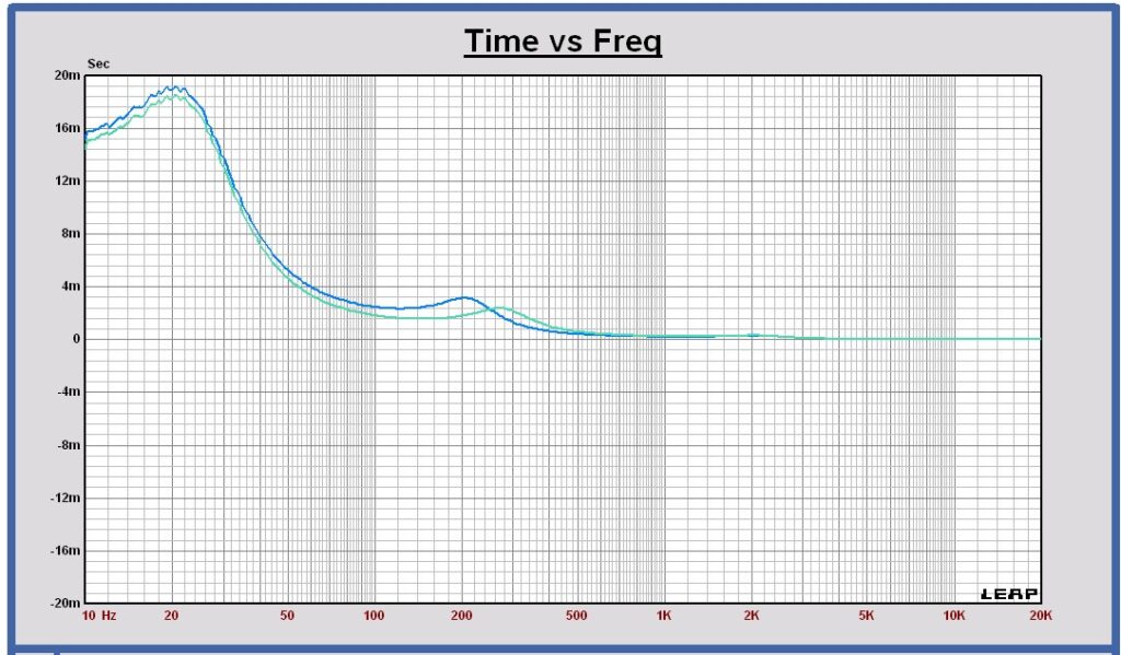
Groupdelay low section in blue, medium section in green
Groupdelay EL5

Groupdelay low section in blue, medium section in green
The group delay of the VCLLabs elliptical filters are not exactly the same for the different filter sections as the phases are not phase aligned in a perfect way for the chosen elliptical targets. The parameters of these filters are optimized in the best way for optimal brickwall behavior, passband ripple, outband slope and flat sum of the filter sections.
New 12th order AP12 All Pole Filter
The AP12 is an even order filter. The low pass and the high pass version each consist of 6 cascaded second order filter sections. They have the same behavior as the Linkwitz-Riley filter family, with a more steep outband roll off.
SPL
Voltage level at the crossover frequency is – 6dB. The SPL sum is flat around the crossover point.
Phase
Low pass and high pass sections are phase aligned and in phase. The group delay has some boost around the crossover frequency.
Power
For frequencies where the distance between the transducer centers becomes close to the wavelength of the sound, there is a small power dip at the crossover frequency.
Polar
A symmetric vertical polar diagram around the on axis at the crossover frequency, if the distance between the transducer centers becomes close to the wavelength of the sound. The SPL is maximum on axis, there is no SPL boost off axis.
Example AP12 targets
Targets 3 way AP12 at 250 – 2500 Hz @ F3 = 25 Hz B3 highpass
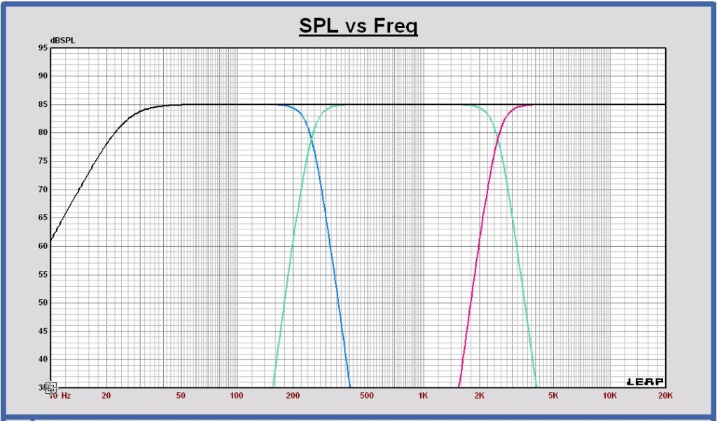
Groupdelay AP12
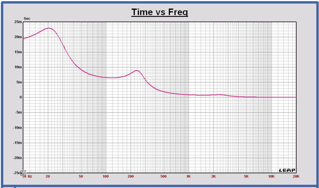
The group delay of the different filter setions is exactly the same for this AP12 filter.
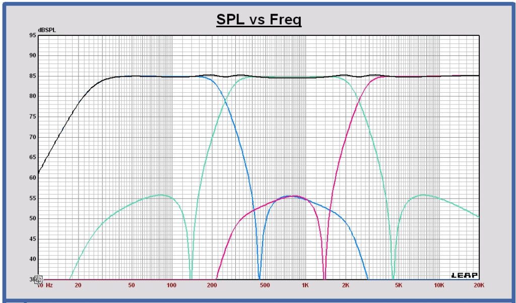
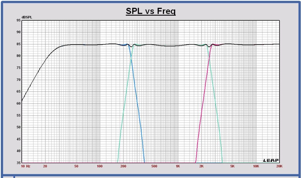
Comparison SPL curves AP12 filter with LR8 and EL5
AP12 (red), LR8 (green) and EL5 (blue) at 250 and 2500Hz — 5 dB / div
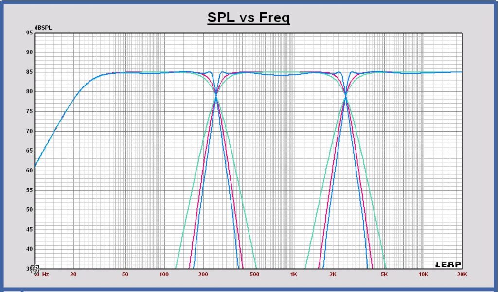
AP12 (red), LR8 (green) and EL5 (blue) at 250 and 2500Hz — 10 dB / div

The curve slope differences in the stopband can be observed. The new AP12 almost has the same slope as our VCLLabs EL5, but the AP12 outband reduction is better.
Some considerations about high slope filtering
Less overlap between the different crossover sections
At the crossover frequency there is an overlap zone where two loudspeaker drivers are operating together. With high slope filtering this zone is smaller. Off axis, the arrival times of the two drivers is different. It means, around the crossover frequency, off axis, an audio signal consists of two components that are shifted in time. With some impact on the room power. In listening tests, we can hear that the high slope filters have a more pure sound than the low slope filters. We think it is caused by the smaller overlap zone of the high slope filters with less time delay errors .
More flat SPL pass band response of each crossover section
Applying high slope filtering, the stopband SPL slopes are much higher. To keep the sum response of two adjacent sections flat, the filter responses show a more brickwall response around the crossover frequency. For high slope filters, the transition from passband to stopband has a higher Q-factor. As a consequence the SPL of each filter section is more flat in the passband, much closer to the crossover frequency. To make the sum response of two operating drivers around the crossover frequency flat, each driver needs much less added value of the other driver. A big advantage of the high slope filters.
Group delay
The higher the filter order, the higher the group delay of each section and the higher the group delay peak at the crossover frequency. Till now, we couldn’t observe a negative impact on the sound performance. To know it for sure, we should make the sum response phase linear with some phase correction. Something to be investigated in the future.
Conclusion
Reducing the overlap zone around the crossover frequency and making the passbands of each filter section more flat, using high slope filters, results in a total audio signal sum with less timing errors. In our opinion the reason why high slope filters sound pure and explosive which results in a very lively natural less colored sound.
Listening tests
Extensive listening tests have been done to compare the high slope crossover filters with each other. We used the VCL DI-215/W dipole speaker, built by Ward De Ceuninck to make several filter designs.
We could compare LR4, LR8, EL3, EL5 and AP12. All filters are crossed at 150 and 2500 Hz.
Crossover Designs used for listening tests
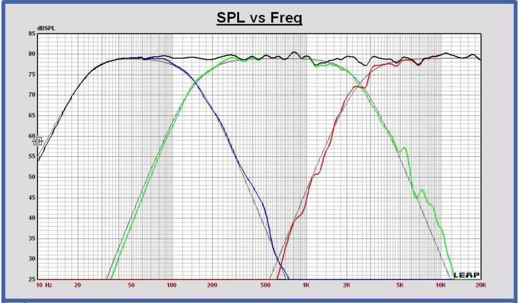
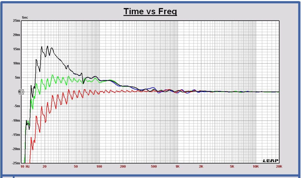
LR4 150 2500 Hz
VCL DI-215/W LR4 at 150 – 2500 Hz SPL at 1m, 2.83Vrms full space
VCL DI-215/W LR4 at 150 – 2500 Hz Groupdelay @ full space
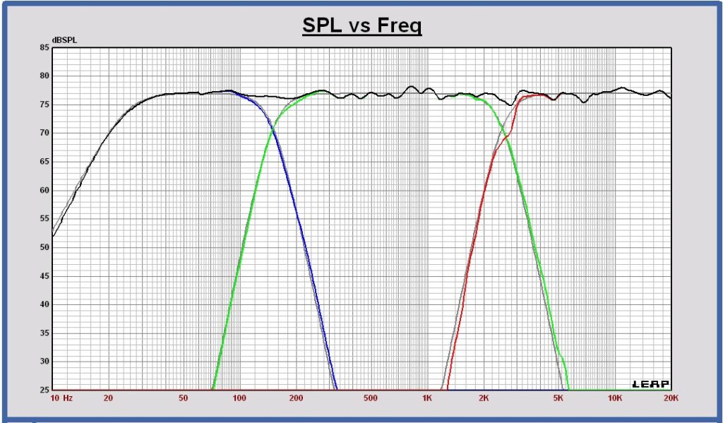
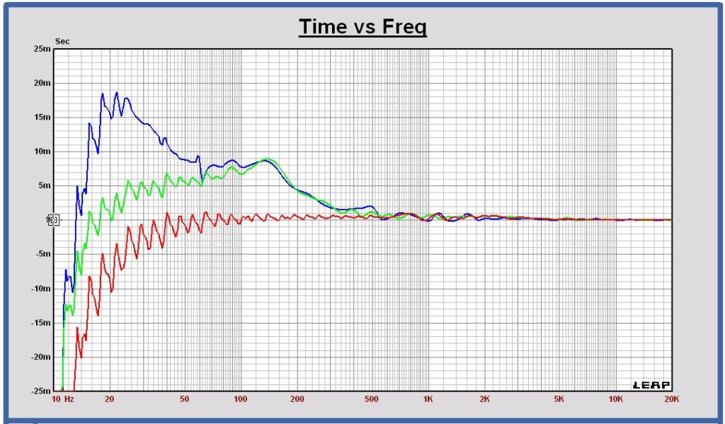
LR8 150 2500 Hz
VCL DI-215/W LR8 at 150 – 2500 Hz SPL at 1m, 2.83Vrms full space
VCL DI-215/W LR8 at 150 – 2500 Hz Groupdelay @ full space
EL3 150 2500 Hz
VCL DI-215/W EL3 at 150 – 2500 Hz SPL at 1m, 2.83Vrms full space

VCL DI-215/W EL3 at 150 – 2500 Hz Groupdelay @ full space

EL5 150 2500 Hz
VCL DI-215/W EL5 at 150 – 2500 Hz SPL at 1m, 2.83Vrms full space
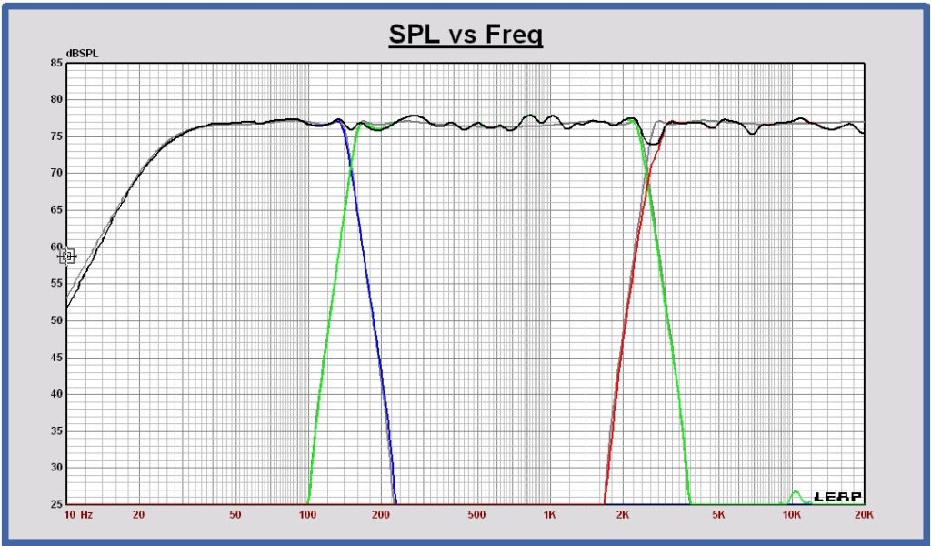
VCL DI-215/W EL5 at 150 – 2500 Hz Groupdelay @ full space
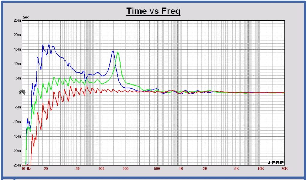
AP12 150 2500 Hz
VCL DI-215/W AP12 at 150 – 2500 Hz @ F3 = 25 Hz — SPL at 1m, 2.83Vrms full space — 5 dB/div

VCL DI-215/W AP12 at 250 – 2500 Hz @ F3 = 25 Hz — SPL at 1m, 2.83Vrms full space — 20 dB/div
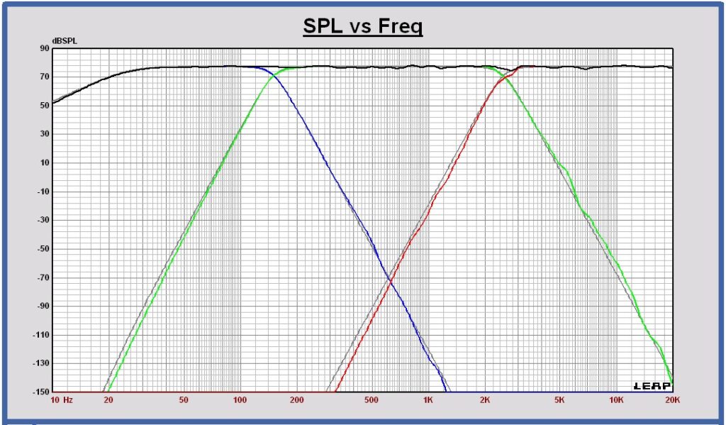
VCL DI-215/W AP12 at 150 – 2500 Hz Groupdelay @ full space
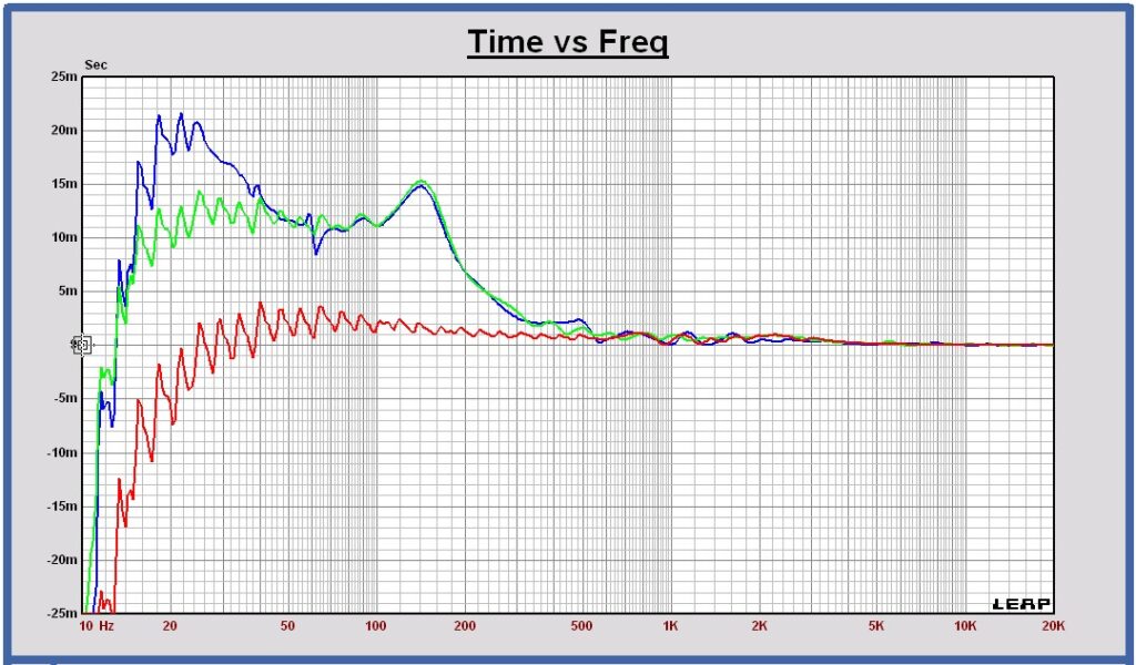
Listening experiences
Ward’s experiences, after extensive listening to the different high slope filter speaker designs, inclusive the new AP12 filter, will be published soon
Realization of the AP12 crossover filter
As the AP12 is a 12th order crossover filter, it consists of six 2nd order generic filter blocks to realize a low pass filter or a high pass filter section. For an AP12 bandpass filter section, twelf 2nd order generic filter blocks are required. Some extra generic filter blocks are needed for the equaling of the loudspeaker drivers. A 3-way AP12 filter also needs more filter blocks than a 2-way version, as the low and high pass sections of a 3-way filter are cascaded filters.
In practice some 2nd order filter blocks can be realized by the acoustical roll off of the drivers at low and high frequencies. In this way the number of generic filter blocks can be reduced.
As a practical design example, the AP12 for the VCL DI-215/W loudspeaker, needed 12 filter blocks for the woofer section, 15 filter blocks for the midrange bandpasss filter section and 8 filter blocks for the tweeter filter.
DSP filter
Once the crossover filter with generic filter blocks is finished, the blocks can be transformed to biquads to be used for a digital IIR filter.
In practice for a 3-way crossover filter, the number of biquads is around 12 for the woofer filter, 16 biquads maximum for the midrange filter and about 8 biquads for the tweeter filter.
So, it is possible to realize the AP12 filter with DSP’s like miniDSP and Hypex.
ASP filter
In the same way, once the crossover filter with generic filter blocks is finished, the blocks can be transformed to opamp filter blocks to be used for an analog active filter.
In practice for a 3-way crossover filter, the number of opamp stages is around 12 for the woofer filter, 16 stages maximum for the midrange filter and about 8 stages for the tweeter filter.
It becomes an extensive schematic, but it is possible to realize an analog active AP12 filter with opamp filter blocks.
Passive filter
An AP12 passive crossover filter needs a separate design, it cannot be derived out of the crossover design with generic filter blocks. It will become an extensive schematic with a lot of components, much work to make such design, but it is possible to realize it also.
