August 2018, 4-way speaker with miniDSP digital filtering
2 x Eton 11-212 woofer and 1 x Eton 11-212 midwoofer
Accuton C173-6-096E midrange and Seas E0058 Be tweeter

This speaker is a classical 3-way speaker, extended with two separate woofer cabinets to create a powerful 4-way speaker. It will become an active system with a digital X-over filter, implemented on a miniDSP platform.
Contents
- General: specification headlines, speaker system, drivers
- Driver measurements on IEC baffle
- Woofer, midwoofer and midrange closed box system
- Speaker cabinet
- SPL, impedance and power responses of the drivers in the cabinet
- Crossover filter design with miniDSP 4x10HD
- Maximum excursion and required amplifier power with LR4 filter
- Speaker building
- Indoor measurements of the drivers mounted in the cabinet
General: specification headlines, speaker system, drivers
This 4-way speaker is a modular concept consisting of 3 cabinets. One cabinet for midwoofer, midrange and tweeter and two cabinets with one woofer each.
The specification headlines are:
- -3dB low frequency response F3 = 30 Hz
- the speaker full space sensitivity at 1m, 2.83Vrms is 83 dB for F3 = 30 Hz, 88 dB for F3 = 40 Hz and 92 dB for F3 = 50 Hz.
- woofers and midwoofer are 11 inch and the midrange 6.5 inch.
- midrange and tweeter are hard cone types, ceramic and beryllium.
- the crossover will have high slope filtering. digital crossover filter implemented on miniDSP 4 x 10 HD cabinet dimensions: heigth 159cm, width 36cm and depth 42cm (height is inclusive the foot)
Speaker system
Closed box system for the woofers, the midwoofer and the midrange.
The crossover filter will be a 5th order elliptical filter. The crossover frequencies 80, 360 and 1620 Hz. Also a Linkwitz-Riley LR4, A Butterwoth B3 and an elliptical 3rd order filter will designed to compare with each other.
Drivers
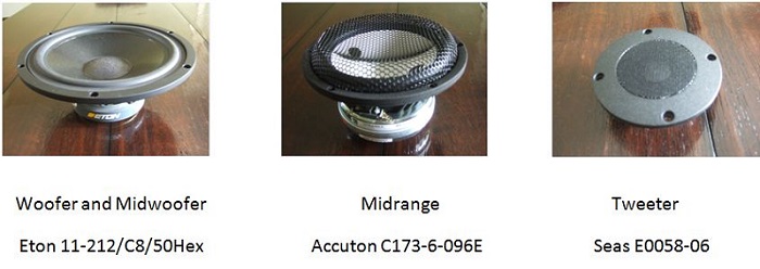
Eton Symphony 2 11-212/C8/50Hex, Accuton C173-6-096E, Seas Excel E0058-06
Cabinet
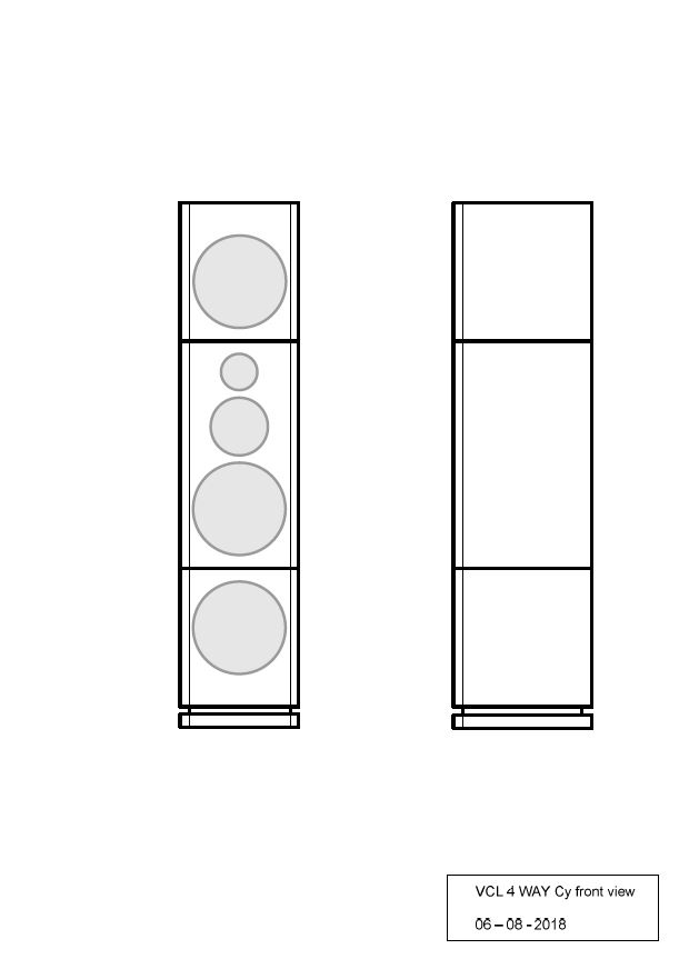
A first impression how the cabinet will look like and how the position of the drivers is chosen. The total cabinet has three parts, the woofer cabinets are positioned under and on top of the midwoofer – midrange – tweeter cabinet.

Driver measurements on IEC baffle
All the drivers are already at home. So the SPL and impedance responses vs. frequency on our IEC baffle are measured. Out of this measured data the exact TSP of our drivers are derived and their infinite baffle models in Leap are created for further simulations of the drivers in the cabinet.
Eton 11-212
Eton 11-212 on the IEC baffle
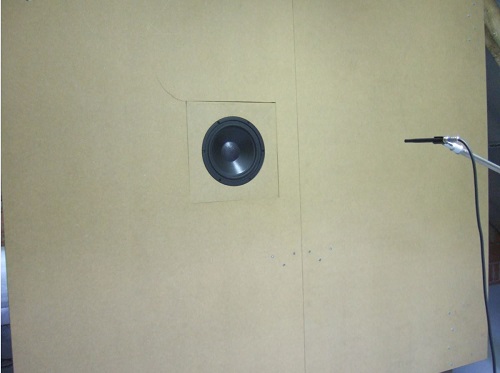
Eton 11-212 SPL and Impedance vs. Freq on IEC baffle

Eton 11-212 SPL and Impedance vs. Freq of the Leap model

The green curve is the IEC baffle measurement and the black curve the specification data.
Accuton C173-6-096E
Accuton C173-6-096E on the IEC baffle
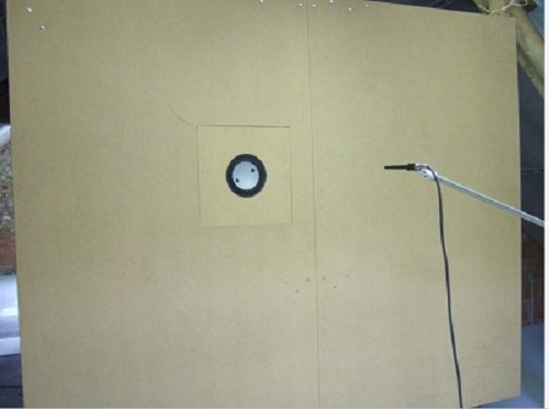
Accuton C173-6-096E SPL and Impedance vs. Freq on IEC baffle

Accuton C173-6-096E SPL and Impedance vs. Freq of the Leap model

The green curve is the IEC baffle measurement and the black curve the specification data
Seas Excel E0058
Seas Excel E0058 on the IEC baffle
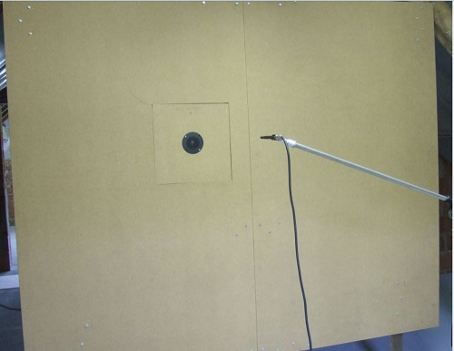
Seas Excel E0058 SPL and Impedance vs. Freq on IEC baffle

Seas Excel E0058 SPL and Impedance vs. Freq of the Leap model

The green curve is the IEC baffle measurement and the black curve the specification data
Woofer, midwoofer and midrange closed box systems
For all, woofer, midwoofer and the midrange closed box systems are used. For the midwoofer and the midrange to avoid internal cabinet resonances, for the woofer to have a perfect phase match with the midwoofer.
Woofer system
The woofer will be used in the frequency region up to 80 Hz. The 11 inch Eton Symphony 2 11-212/C8/50Hex is chosen. It has a 91 dB sensitivity at 1 m, 2.83 Vrms on infinite baffle, fs = 24 Hz, Qts = 0.31, Vas = 134 litres and the maximal excursion is 5 mm peak.
The woofer is placed in a closed box of 42 litres, that will be heavy filled with sheep wool to realize a good internal cabinet damping. In this 42 litres cabinet the system resonance frequency fc is 42 Hz and the system Q factor is 0,58.
Midwoofer system
The midwoofer will be used in the frequency region 80 to 360 Hz. The same 11 inch as the woofer Eton Symphony 2 11-212/C8/50Hex is chosen.
The midwoofer is placed in a closed box of 50 litres, that will be heavy filled with sheep wool to realize a good internal cabinet damping. In this 50 litres cabinet the system resonance frequency fc is 40 Hz and the system Q factor is 0,54.
Midrange system
The midrange will be used in the frequency region 360 to 1620 Hz. The 6.5 inch Accuton C173-6-096E is chosen. It has a 91.5 dB sensitivity at 1 m, 2.83 Vrms on infinite baffle, fs = 53.8 Hz, Qts = 0.26, Vas = 13.8 litres and the maximal excursion is 5 mm peak.
The midrange is placed in a closed box of 18 litres, that will be heavy filled with sheep wool. In this 18 litres cabinet the system resonance frequency fc is 61Hz and the system Q factor is 0,29.
Speaker cabinet
The cabinet is a tower concept and consists of three parts. A medium cabinet for midwoofer, midrange and tweeter and two woofer cabinets, one at the bottom and one at the top.
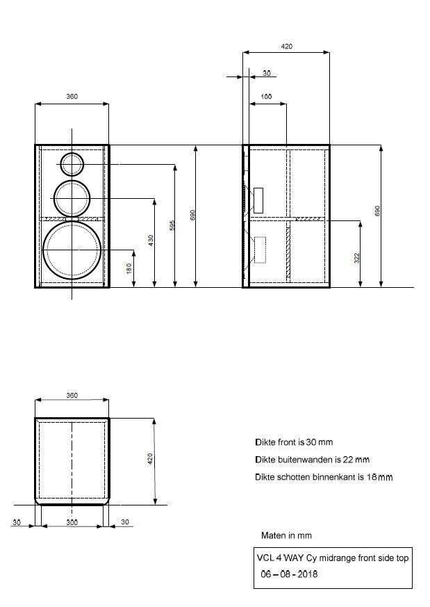
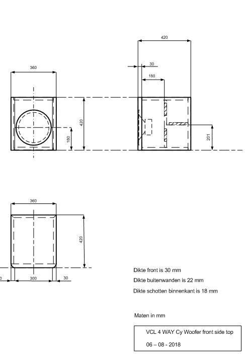
The total speaker dimensions are W x H x D = 36 x 153 x 36 cm. The speaker foot is 6cm high.
The front panels are 30 mm thick and all the other walls 22 mm. The internal bracing will be made 18 mm.
Acoustical damping plates will be fixed against the internal sides of the walls.
Several pictures of the cabinet will be published later in this blog.
Drawing and dimensions of the medium cabinet
Drawing and dimensions of the woofer cabinet
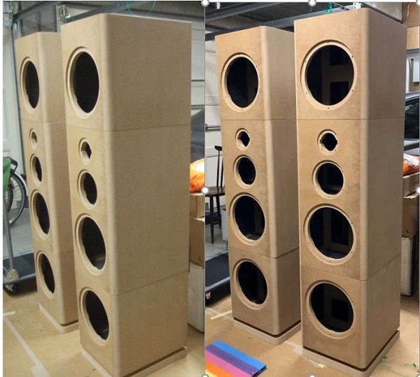
Total cabinet look
SPL, impedance and power responses of the drivers in the cabinet
Based on the SPL and TSP data out of the IEC baffle measurements, driver models on infinite baffle were created in Leap.
These driver models are placed in the speaker cabinet model and the SPL, power and impedance are simulated. These responses will be used for the design of the crossover filter.
Once the cabinets are ready these responses in enclosure will be measured and compared with these simulated results.
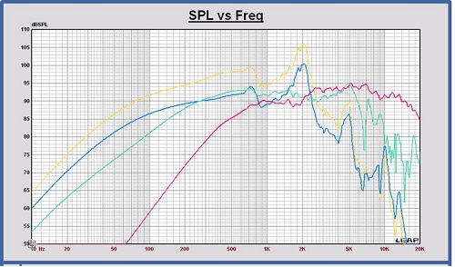
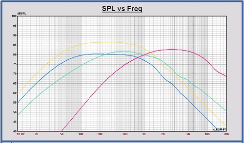
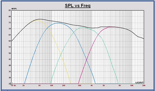
Curves of woofer in yellow, midwoofer in blue, midrange in green and tweeter in red.
SPL of the drivers in the cabinet at 1m, 2.83 Vrms in full space
Impedance of the drivers in the cabinet at 2.83 Vrms

Power of the drivers in the cabinet at 1m, 2.83 Vrms
Crossover filter design with miniDSP 4x10HD
We use miniDSP for this project, we have chosen the 4x10HD type.
The miniDSP 4x10HD has 2 stereo analog inputs (both RCA and balanced), 2 stereo digital inputs (SPDIF, AES-EBU and TOSLINK), 4 stereo analog outputs (both RCA and balanced) and 2 digital outputs (AES-EBU and SPDIF).
There is also a digital volume control that can be remote controlled.
So, our 4-way can be build with the miniDSP 4x10HD without any problem. Using the miniDSP digital platform for this speaker, allows to compare several types of crossover filtering w.r.t. the sound performance of the different configurations.
For this study we have designed the classical Linkwitz-Riley 4th order filter. Later on in the project we will make more filter types like Butterworth and Elliptical filters and also different orders of filtering. More about this in later posts when the speaker will be ready to be used.
For every crossover filter design, we investigate many of the speaker responses, SPL on and off axis, power, maximum excursion, SPL limit, required amplifier power, impedance (in case of passive filtering),…
Crossover frequencies
Looking to the power responses in our previous post of September 09, shows that the 11 inch woofer can be used up to about 500 Hz and the midrange up to maximum 2kHz. Woofer and midwoofer will be crossed at 80 Hz, woofer and midrange at 360 Hz, midrange and tweeter at 1620Hz.
Filter Targets
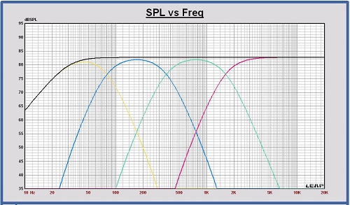
These are the LR4 flter targets we like to realize. The low frequency response target is a Butterworth 2nd order high pass filter response at 30 Hz.
SPL targets LR4 filter 80 – 360 – 1620 Hz
Digital filter design with miniDSP
MiniDSP has an advanced ‘custom biquad programming’ mode. To calculate the biquad coefficients we use Leap X-overShop. The crossover design is done with standard analog functional blocks. Once the design is completely ready, the analog functional blocks are transformed to digital biquad filters using a bilinear transform. The configuration file is created to be imported in miniDSP. The delay times to compensate for the acoustical offset between the drivers, will be set seperately in miniDSP as the final step.
How a X-over design for a digital platform like miniDSP is done, will be descibed in detail in one of our next posts.
The results
In the plots, the SPL, the power and the off axis responses of this LR4 filter design.
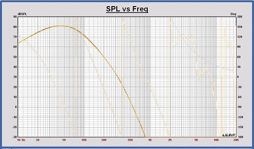
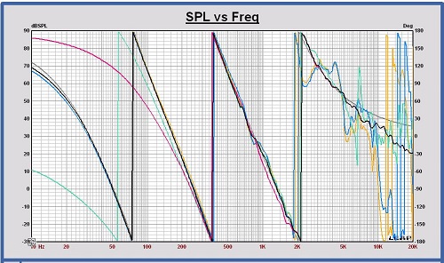
To show how precisely the SPL of each driver can be designed on its target with the digital design in miniDSP, the plots are shown for each driver apart. The SPL is shown on a 120 dB plot range to show how deep the responses are designed on target. The phase response and its target are also added to see the good phase mapping on target in the driver operating ranges.
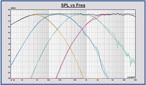
It results in a nice combined SPL response, the phase aliging is very good.
Woofer SPL and phase on axis responses – LR4 filter
Midwoofer SPL and phase on axis responses – LR4 filter
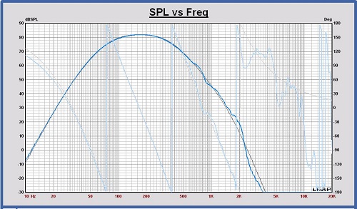
Midrange SPL and phase on axis responses – LR4 filter
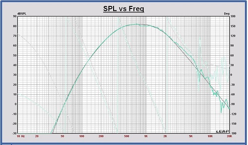
Tweeter SPL and phase on axis responses – LR4 filter
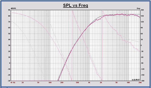
Combined SPL on axis response – LR4 filter
Combined phase on axis response – LR4 filter
Combined Power response – LR4 filter
To show the off axis response, the combined midrange and tweeter horizontal SPL on and off axis reponse is calculated in the next plot.
Combined midrange and tweeter horizontal SPL on and off axis response – LR4 filter
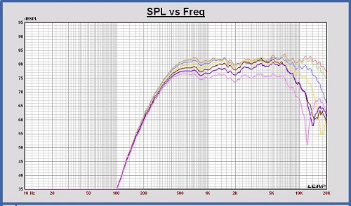
0 degree in red
15 degree H in green
30 degree H in blue
45 degree H in yellow
60 degree H in brown
75 degree H in violet
90 degree H in pink
Maximum excursion and required amplifier power with LR4 filter
Maximum excursion
With the designed LR4 filter, the woofer has its maximum excursion of 5 mm peak at 30 Hz for a voltage of 11.7 Vrms at the input of the filter. This results in a maximum system SPL of 95.3 dB at maximum excursion of the woofer.
The excursion of midwoofer, midrange and tweeter have been calculated also at 11.7 Vrms.
Excursion at 11.7 Vrms of woofer(yellow), midwoofer (blue), midrange(green) and tweeter(red)
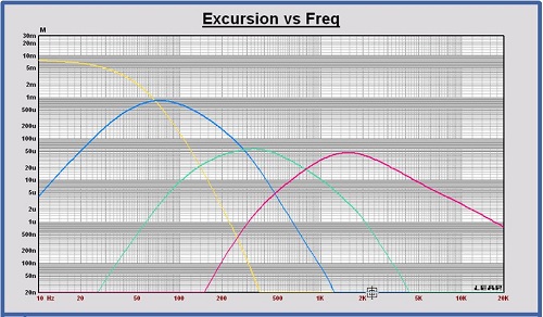
The woofer has its maximum excursion of 5 mm peak at 30 Hz. The maximum specified excursion of the Eton 11-212 is 5 mm peak.
The midwoofer excursion is maximum at 72 Hz and is equal to 0.82 mm peak. The maximum specified excursion of the Eton 11-212 is 5 mm peak.
The midrange excursion is maximum at 339 Hz and is equal to 36 um peak. The maximum specified excursion of the Accuton C173-6-096E is 5 mm peak.
The tweeter excursion is maximum at 1557 Hz and is equal to 46 um peak. The maximum specified excursion of the Seas E0058-06 is 250 um peak.
Required power
For each driver the required amplifier power is calculated at maximum excursion of the woofer. That is at 11.7 Vrms at the input of the filter and at a maximum SPL level of 95.3 dB at 1m.
Required power of woofer(yellow), midwoofer(blue), midrange(green) and tweeter(red) at 14.15 Vrms input filter
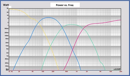
The woofer power is maximum at 30 Hz and equal to 17.6 W.
The midwoofer power is maximum at 144 Hz and equal to 6.5 W.
The midrange power is maximum at 673 Hz and is equal to 1.3 W.
The tweeter power is maximum at 20 kHz and is equal to 3.6 W.
Impedances of woofer(yellow), midwoofer(blue), midrange(green) and tweeter(red)
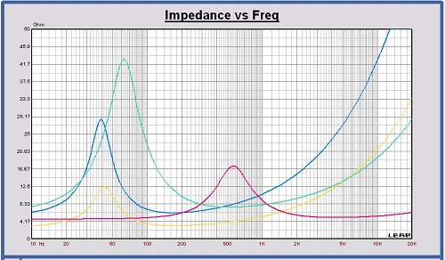
Looking to the driver impedances, the minimum required amplifier power for the drivers can be specified as follows:
17.6 W in 7.2 Ohm for the woofer; 6.5 W in 6.2 Ohm for the midwoofer; 1.3 W in 7.6 Ohm for the midrange and 3.6 W in 6.3 Ohm for the tweeter.
Speaker building
The construction of the speaker has been started last month. Some pictures of the building progress.
The speakers are already playing with a digital crossover implemented in the miniDSP 4x10HD.
More about some measurements and how the crossover is programmed in miniDSP in later posts.
Internal bracing and wall damping
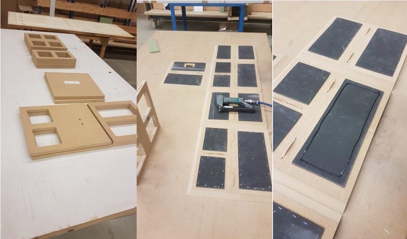
Backside panel – Midrange cabinet without front panel
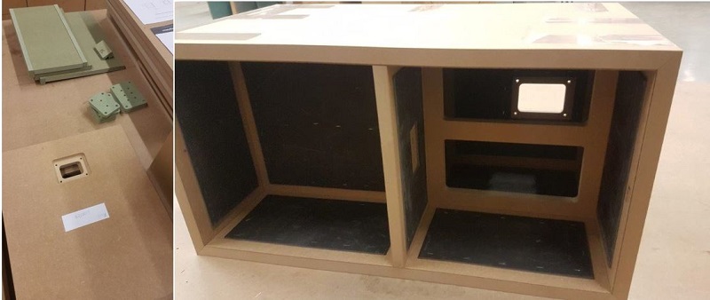
Speaker cabinets ready
Internal wiring of midrange and woofer cabinets

Binding posts connections of midrange and woofer cabinets

Cabinet filling with sheep wool

Driver mounting in the cabinet

Speaker modules ready to make 2 speaker towers
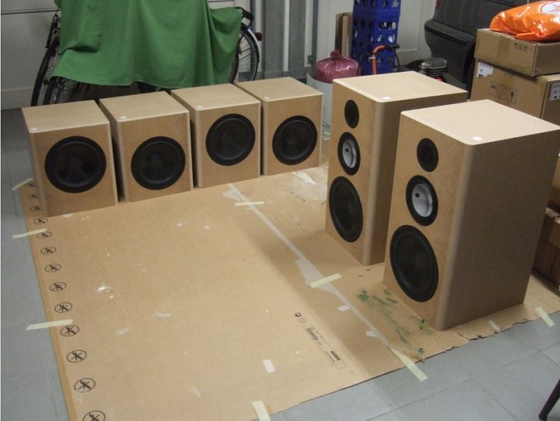
The speakers in our listening room

Indoor measurements of the drivers mounted in the cabinet
All drivers were already measured on IEC baffle and with these measurements infinite baffle models of the drivers were made.
These models were used to simulate the SPL and impedance responses of the drivers mounted in the cabinet.
As a check for these simulations, we did some indoor measurements of the drivers in the cabinet.
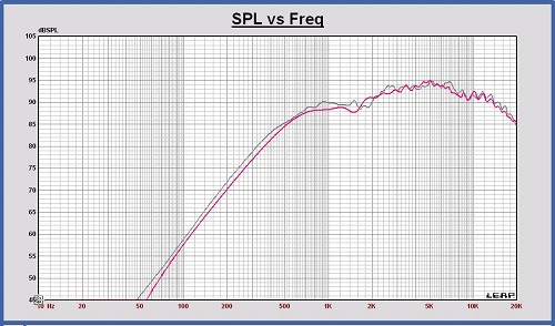
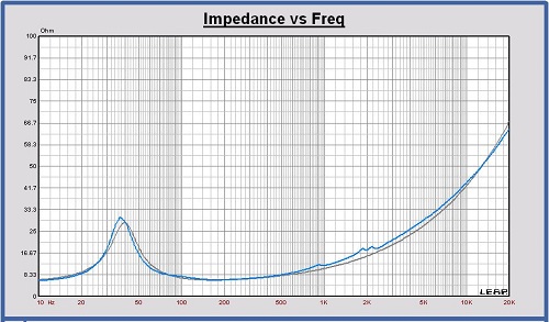
In the following plots the measurements and the simulations are compared for all drivers.
Midwoofer in cabinet, SPL measurement and simulation, 1m on axis, 2.83 Vrms
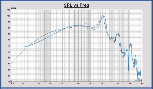
Midrange in cabinet, SPL measurement and simulation, 1m on axis, 2.83 Vrms

Tweeter in cabinet, SPL measurement and simulation, 1m on axis, 2.83 Vrms
Midwoofer in cabinet, impedance measurement and simulation, 2.83 Vrms
Midrange in cabinet, impedance measurement and simulation, 2.83 Vrms
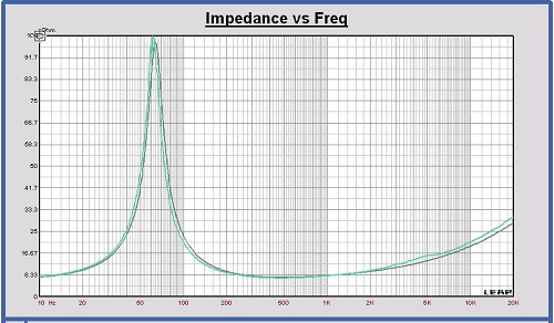
Some comments
Comparing SPL measurements and simulations, some differences can be seen below 1 kHz. It is caused by the low anechoic gate time for the FFT of an indoor measurement. Also the simulation is a little different at frequencies where the radiating of the speaker becomes ominidirectional below 1 kHz.
For the crossover design some curve splicing is done of low frequency simulations and high frequency measurements. The splicing frequency is chosen around 400 Hz.
