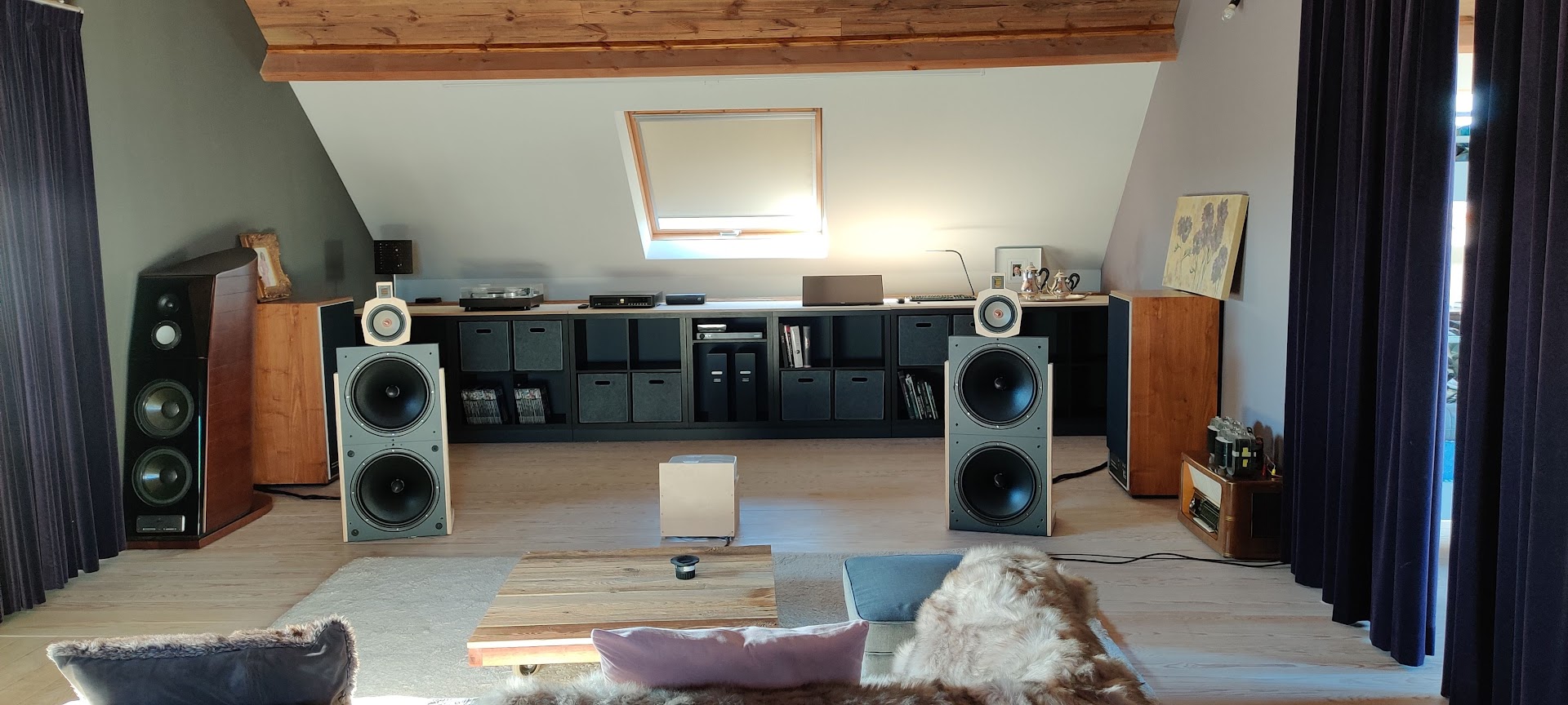
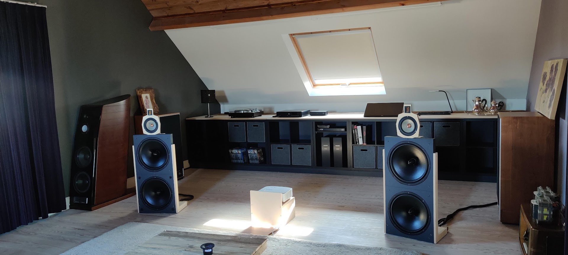
January 2022 – VCL DI-215/W, a 3-way full range dipole speaker with 2 AE woofers, Seas Excel midrange and Mundorf AMT dipole tweeter
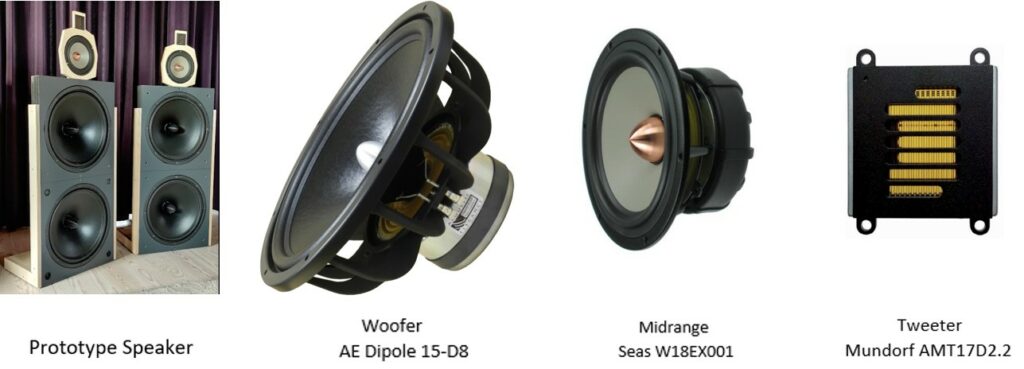
- The VCL DI-215/W is a 3 – way full range dipole loudspeaker built by Ward De Ceuninck. Ward is co-owner and designer at MONOLITH Magnetics and a good friend. VCLLabs has done for him the investigation of the dipole system and the design of the digital crossover filter.
- The transducers are two Audio Elegance Dipole 15 – D8 as woofer, the Seas W18EX001 as midrange and the Mundorf AMT17D2.2 as tweeter.
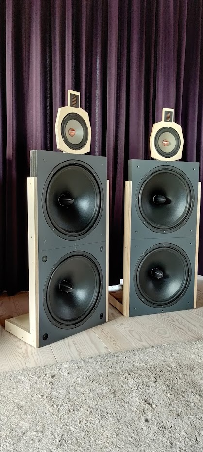
- The total speaker is 120 cm high and 48 cm wide. The loudspeaker foot is 30 cm deep.
- The speaker sensitivity is 85 dB at 1m, 2.83 Vrms, full space, the low frequency response F3 = 25 Hz and for a woofer maximum excursion condition at 25 Hz the speaker maximum SPL is 98 dB @ 25 – 20000 kHz at 1m, free space.
- Using the simulation results of the SPL and power responses, a LR4 digital crossover for a miniDSP platform has been designed. The speaker is playing and the listening tests are excellent.
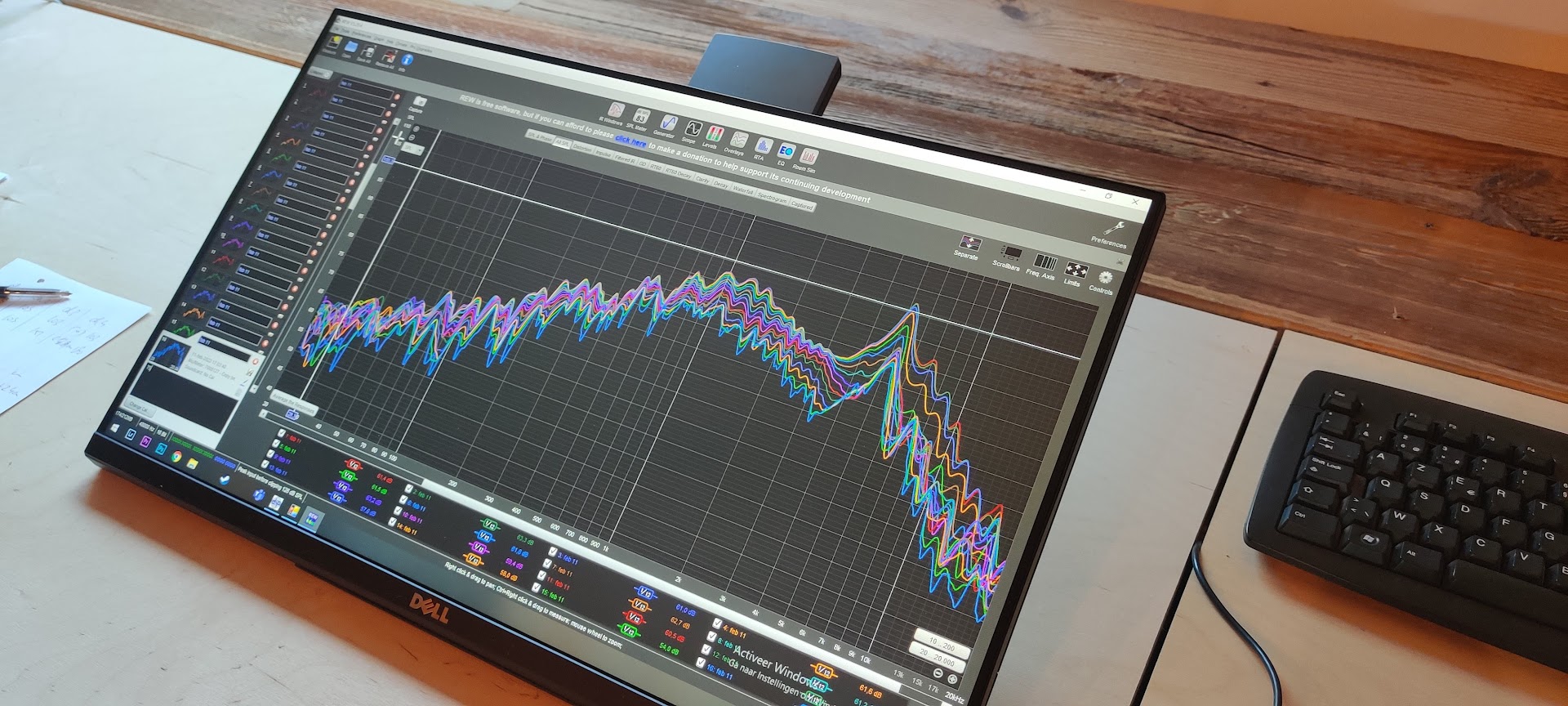
- Acoustical measurements are done. They are important for a dipole speaker as the front and back radiation for a transducer mounted in a baffle are not the same. The crossover filter is adapted to its final version.
Contents
- The never ending quest for the ultimate loudspeaker…
- Specification Headlines
- Transducers
- Cabinet
- Dipole radiation behavior of the transducers in the cabinet
- Woofer Dipole
- Midrange Dipole
- Tweeter Dipole
- Active Digital Crossover filter
- Maximum excursion and maximum SPL with crossover filter
- On axis ground plane measurements
- Off axis ground plane and free space measurements
- Update Active Digital Crossover filter using SPL measurements
- Harmonic distortion improvement of the midrange transducer
- Gallery
- Listening
The never ending quest for the ultimate loudspeaker…
Ward’s motivation and inspiration to build this speaker:
” Although I have a few pretty good audio systems, there is always room for novel ideas.
Some years ago, I read some articles from the famous Dr. Floyd Toole in which he describes what we are actually listening to, how we perceive music. It boils down to the fact that we are actually listening to a mix of the acoustic emitted power and SPL over a broad range of frequencies and he clearly prefers speakers that have an SPL and power response that are in sync. That is also the reason that two speakers with an identical SPL behavior can sound totally different.
For my taste, most well engineered monopole speakers give me the impression of a somewhat boosted bass response which is partly due to the 6 dB lift towards lower frequencies because of the transition of a 2PI to 4PI space. A speaker is typically designed for flat SPL in full space which results in a 6dB power increase at the lower frequencies. So power and SPL are not in sync.
On the contrary, a dipole speaker is able to fulfill this requirement. Power and SPL can be matched to each other in a very broad frequency range from say 20 Hz up to 5 kHz. Other benefits include the fact that standing waves are less excited which leads to better readability of the lower notes and there is also no enclosure which is smearing out the perceived audio signal. Therefore I decided to move towards a dipole concept. There is however a major hurdle to be taken as this is not an easy project to accomplish.
My dear friend Paul agreed to do the design of this particular speaker using LEAP as he also showed interest in the dipole speaker concept as such. Some preliminary investigation using Leap showed us the way. We should make use of very small baffle sizes in order to preserve the benefits of the dipole operation.
Selection of drivers
The selection criteria for the woofer section were pretty obvious: large surface, high xmax , high SPL, rather high Q. This enables us to get a really low F-3 point and still have a good sensitivity. The choice was pretty easy as Acoustic Elegance is actually producing excellent low distortion long stroke woofers with rather light membranes. It also has a reputation on its own. I opted for two AE Dipole D15 8 Ohm woofers per channel as I have a pretty large listening room. My system is active and each woofer has a dedicated amplifier. This leads to a very good sensitivity which was needed as I wished to have a very low frequency extension of 25 Hz. Paul also checked the max SPL levels that can be obtained and the frequency at which dipole operation is guaranteed.
The midrange unit is a 6.5i Seas Excel W18EX001 unit with a magnesium cone which suits dipole operation from 200 Hz up if needed. Although the design of the unit is already 20 years old, it still has some good specifications with respect to THD and other essential parameters. Essentially, the unit is able to work as a true piston in a broad frequency range. Severe breakup is taking place at around 5 kHz. That can also be observed in the 3rd order harmonic distortion at around 1.65 kHz which is in the passband of the driver. Paul suggested taming down this resonance by a parallel LCR circuit in series with the unit to drastically reduce the distortion. This simple passive addition changes the voltage drive into a current drive at the frequencies of interest , thereby lowering distortion substantially.
The tweeter unit is the recently introduced Heil Motion Mundorf AMT17D2.2 which is intended for freestanding operation. The rear output exactly matches the front output which is of course desirable. It is a very small unit for a ribbon driver and therefore it does not suffer from poor vertical dispersion.
I also indicated to Paul that I have a preference for LR4 X-over filters.This filter type enables a good compromise between technical excellence and good subjective evaluation.
The execution is made easy but making use of digital X-over platform. As we are living in a different location, this is very handy as an updated design consists of a file containing biquads.
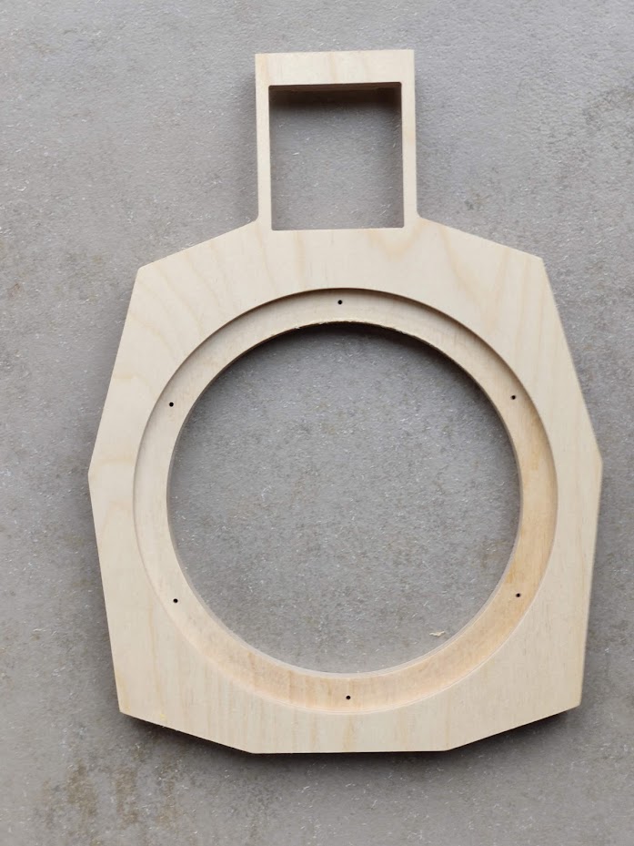
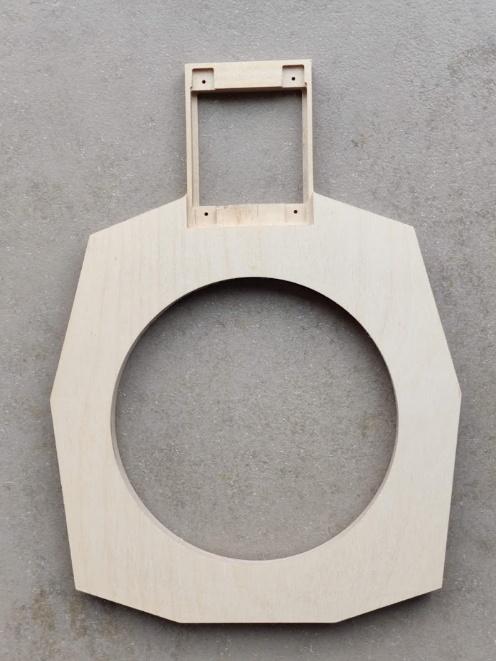
I made the prototype speaker which is pretty easy to achieve. For the mid / high baffle I made use of a CNC milling service. All the rest of the process was what I would call pretty straightforward. “
Specificaton Headlines
- System: 3-way full range dipole with a digital active X-over using miniDSP
- Woofer: 2 x AE Dipole 15-D8
- Midrange: Seas W18EX001
- Tweeter: Mundorf AMT17D2.2
- Low frequency response: F3 = 25 Hz
- Sensitivity: 85 dB at 1m, 2.83 Vrms, full space
- SPL at maximum excursion, 25 – 20000 Hz: 98 dB, 1m, full space
- Crossover: Linkwitz – Riley 4th order at 250 and 2500 Hz
- Impedance: tbd
- Baffle dimensions with foot: width x heigth x depth = 48 cm x 120 cm x 30 cm
Transducers
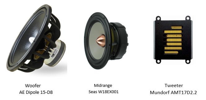
AE Dipole 15-D8, Seas W18EX001, Mundorf AMT17D2.2
For the woofer two 15 inch transducers AE Dipole 15-D8 in parallel are used. These transducers are specially designed for dipole applications and if placed in a 48 cm wide open baffle they can be used up to 250 Hz as a dipole configuration without any problem. With their high sensitivity of 94.0 dB @ 2.83 Vrms, 1m and its high maximal lineair excursion of 15 mm peak, they are very suitable to be used in this 3 way dipole loudspeaker.
As midrange the 6.5 inch Seas W18EX001 is chosen. The sensitivity is 88 dB at 2.83 Vrms. Placed in a very small open baffle this transducer can operate as a dipole up to 2500 Hz.
The Mundorf AMT17D2.2 is an AMT dipole tweeter. The radiating surface Sd = 12 cm2. The diaphragm is about 25 mm wide and 50 mm high. The harmonic distortion of this transducer is low, better than -40 dB between 2700 and 20000 Hz. The transducer can be used as a dipole tweeter without baffle. The tweeter flange is 60 mm wide and 60 mm high.
Cabinet
Cabinet dimensions

Dipole radiation of the transducers in the cabinet
Some study has been done to investigate the dipole radiation behavior of the transducers in the cabinet. On and off axis SPL responses have been simulated and the polar diagram, the power response and the direcivity index are considered in detail.
For a good dipole behavior in the total frequency range, the polar diagram has to be uniform conform the dipole characteristics and the directivity index (DI) has to be about 4.7 dB and as flat as possible versus frequency.
To calculate the power response and directivity index, the horizontal and vertical SPL off axis responses of the woofers, the midrange and the tweeter are simulated in steps of 15 degrees, the speaker placed in a full sphere at 3m distance. The power is calculated out of the mean value of these curves. The power is represented as the SPL of an omnidirectional source at 3m distance in a full sphere with a SPL value equal to the power.
To guarantee a good dipole behavior of all the transducers in their operating frequency range, the baffle size is chosen as small as possible w.r.t. the transducer frame dimensions.
Woofer Dipole
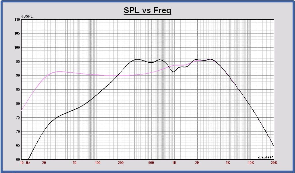
Simulation in Leap on a baffle with dimensions W x H = 578 x 900 mm. The baffle width for the Leap simulation is calculated as the actual baffle width of 470 mm plus two times the actual baffle depth of 54 mm.
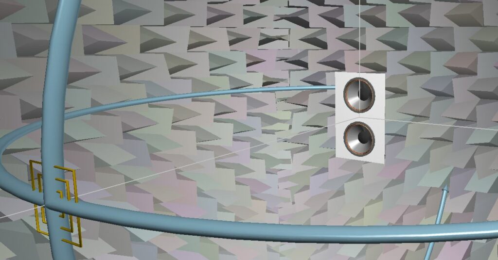
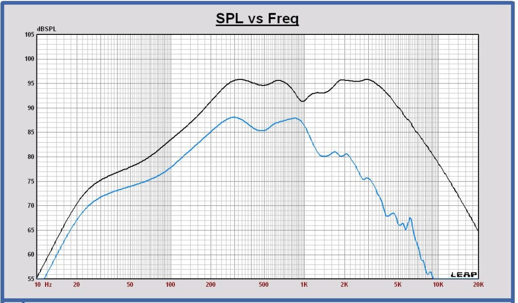
SPL on axis (black) and SPL on infinite baffle (pink) at 3m, 2.83 Vrms in full sphere
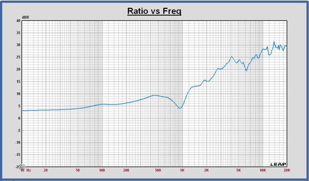
Dipole transfer (blue) compared with +6 dB slope curve (brown)
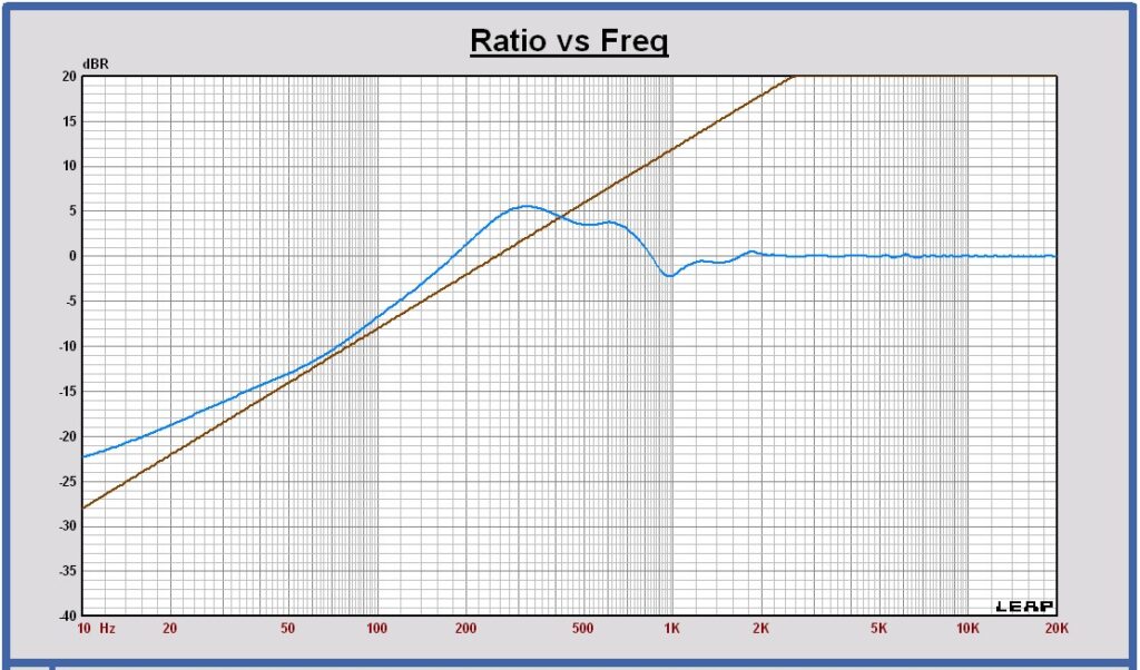
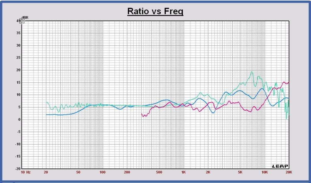
The dipole transfer is the ratio of the SPL on axis over the SPL on infinite baffle. In normal conditions this dipole transfer is a + 6dB slope below the dipole peak. The deviation of the dipole transfer below 50 Hz is caused by a Leap artifact at low frequency low levels. Out of the difference between both curves, some correction can be calculated on the SPL response below 50 Hz.
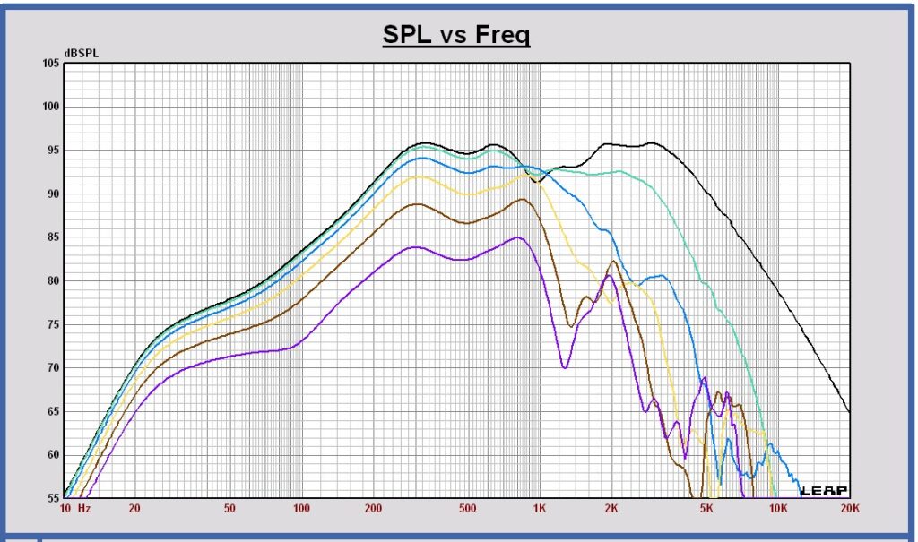
SPL on axis and horizontal off axis 15 30 45 60 75 degrees at 3m, 2.83 Vrms in full sphere
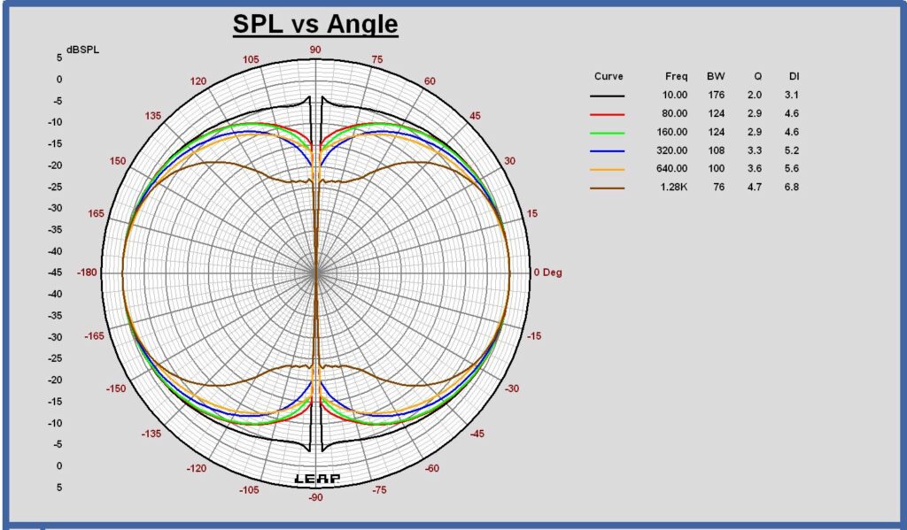
Horizontal polar diagram 10 – 80 – 160 – 320 – 640 – 1280 Hz at 3m in full sphere
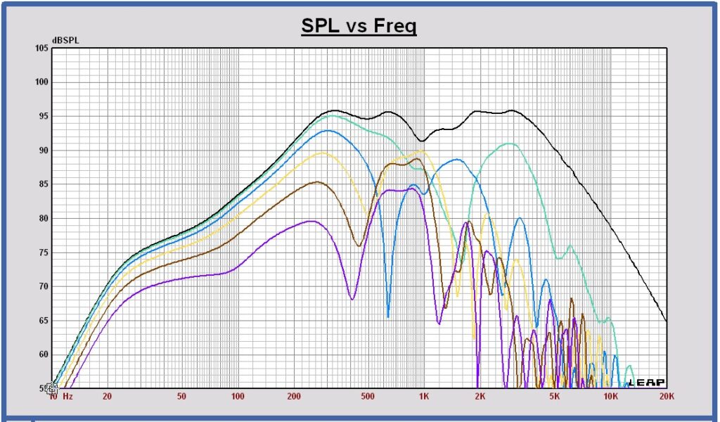
SPL on axis and vertical off axis 15 30 45 60 75 degrees at 3m, 2.83 Vrms in full sphere
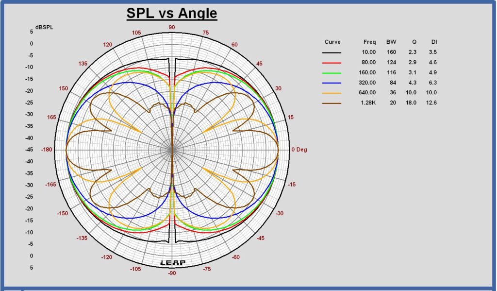
Vertical polar diagram 10 – 80 – 160 – 320 – 640 – 1280 Hz at 3m in full sphere
SPL on axis and the power at 3m, 2.83 Vrms in full sphere
Directivity Index at 3m in full sphere
Remark: the deviation of the low frequency DI from 4.7 dB below 100 Hz is caused by a Leap simulation artifact of the SPL at low frequencies.
Midrange Dipole
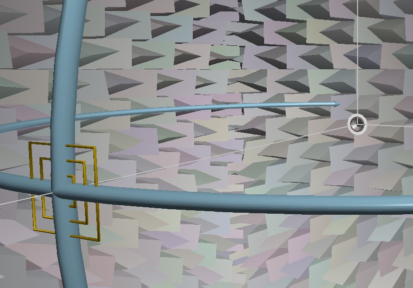
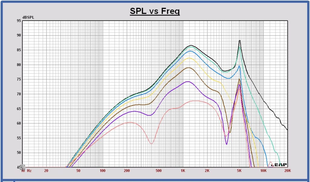
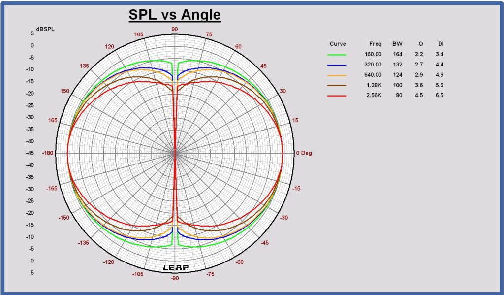
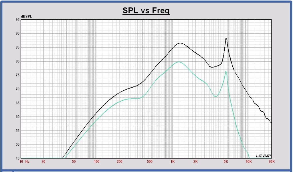
Simulation in Leap on a round baffle with diameter of 200 mm.
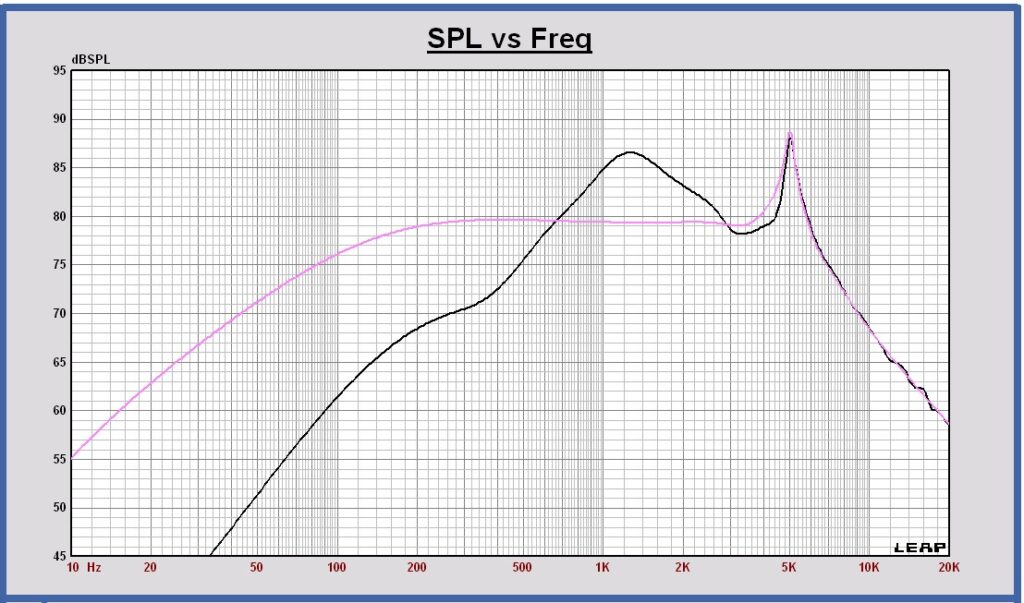
SPL on axis (black) and SPL on infinite baffle (pink) at 3m, 2.83 Vrms in full sphere
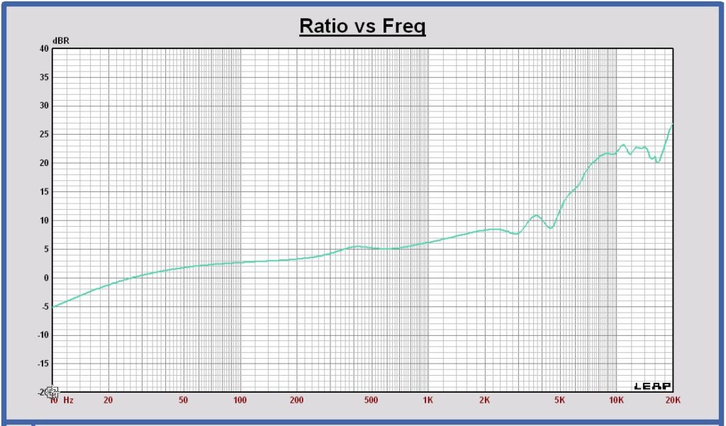
Dipole transfer (green) compared with +6 dB slope curve (brown)

The deviation of the dipole transfer below 200 Hz is caused by a Leap artifact. Out of the difference between both curves, some correction can be calculated on the SPL response below 100 Hz.
SPL on axis and horizontal off axis 15 30 45 60 75 degrees at 3m, 2.83 Vrms in full sphere
Horizontal polar diagram 160 – 320 – 640 – 1280 – 2560 Hz at 3m in full sphere
SPL on axis and the power at 3m, 2.83 Vrms in full sphere
Directivity Index at 3m in full sphere
Remark: the deviation of the low frequency DI from 4.7 dB below 400 Hz is caused by a Leap simulation artifact of the SPL at low frequencies.
Tweeter Dipole
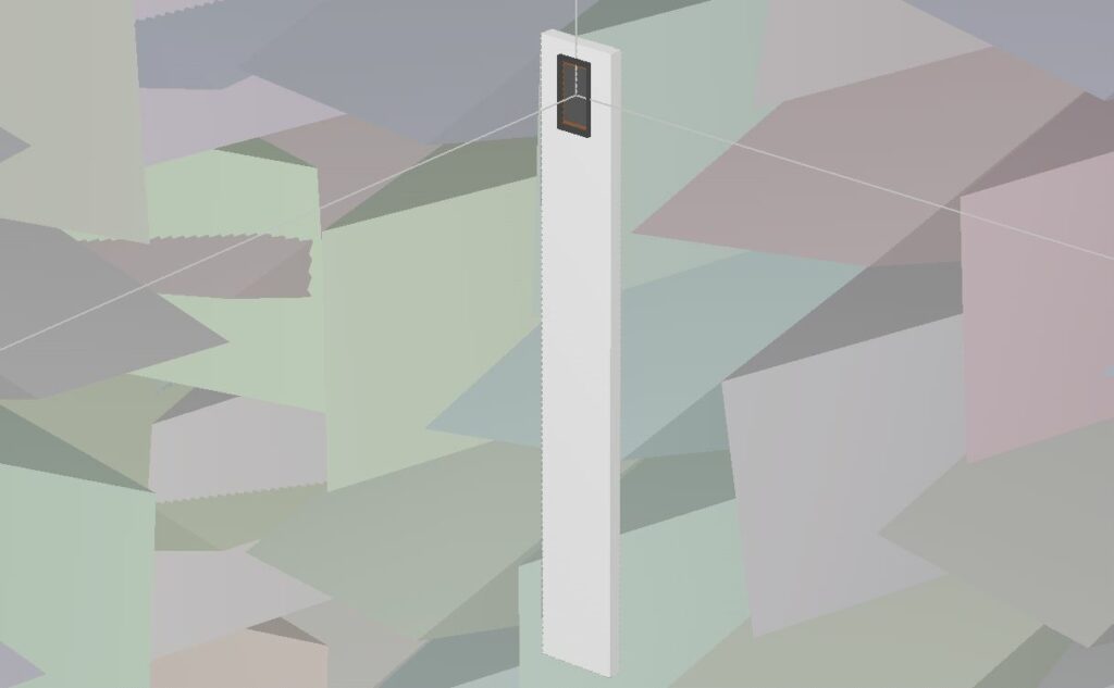
The Mundorf AMT17D2.2 dipole tweeter is chosen. It is a dipole design and is very small, interesting to realize a dipole behavior at high frequencies. The outer flange dimensions of this tweeter are 60 x 60 mm. The tweeter baffle dimensions in Leap are chosen W x H x D = 66 x 500 x 12 mm. The tweeter center is placed at 40 mm from the top of the baffle.
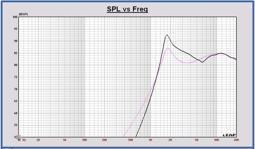
SPL on axis (black) and SPL on infinite baffle (pink) at 3m, 2.83 Vrms in full sphere
Dipole transfer (brown) compared with +6 dB slope curve (red)
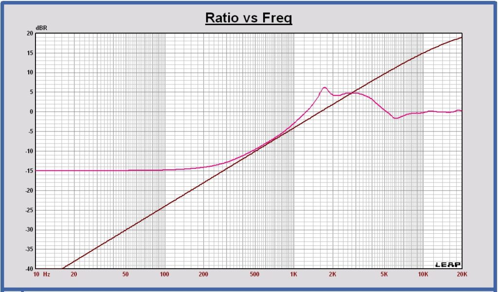
The deviation of the dipole transfer below 500 Hz is caused by a Leap artifact. Out of the difference between both curves, some correction can be calculated on the SPL response below 500 Hz.
SPL on axis and horizontal off axis 15 30 45 60 75 90 degrees at 3m, 2.83 Vrms in full sphere
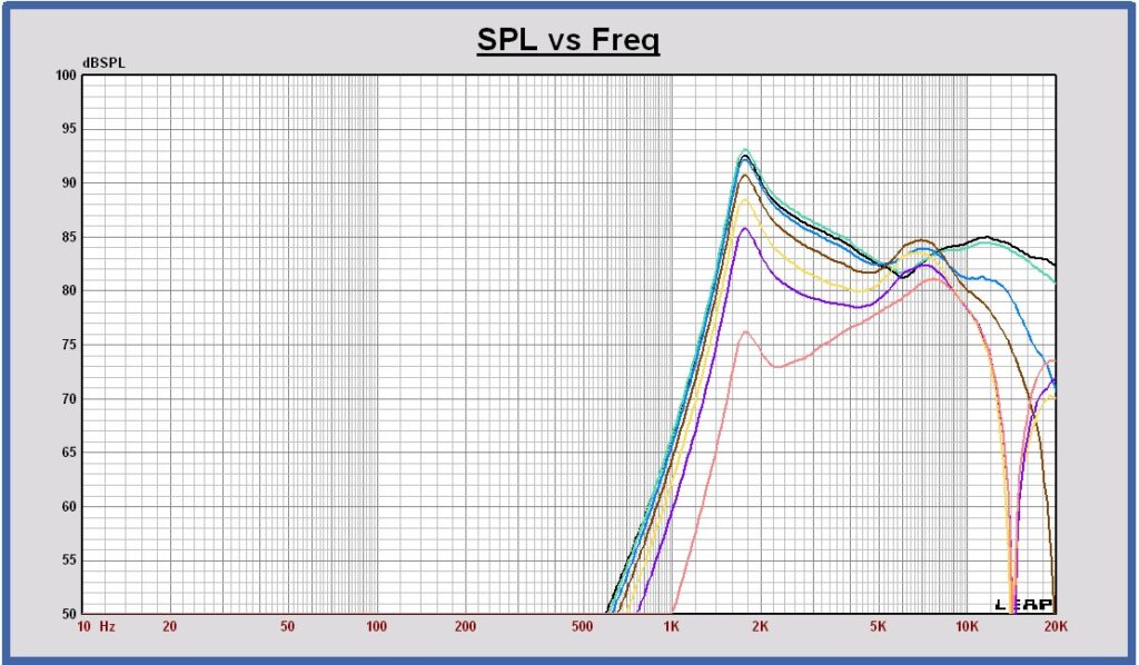
Horizontal polar diagram 1280 – 2560 – 3840 – 5120 – 6400 – 12800 Hz at 3m in full sphere
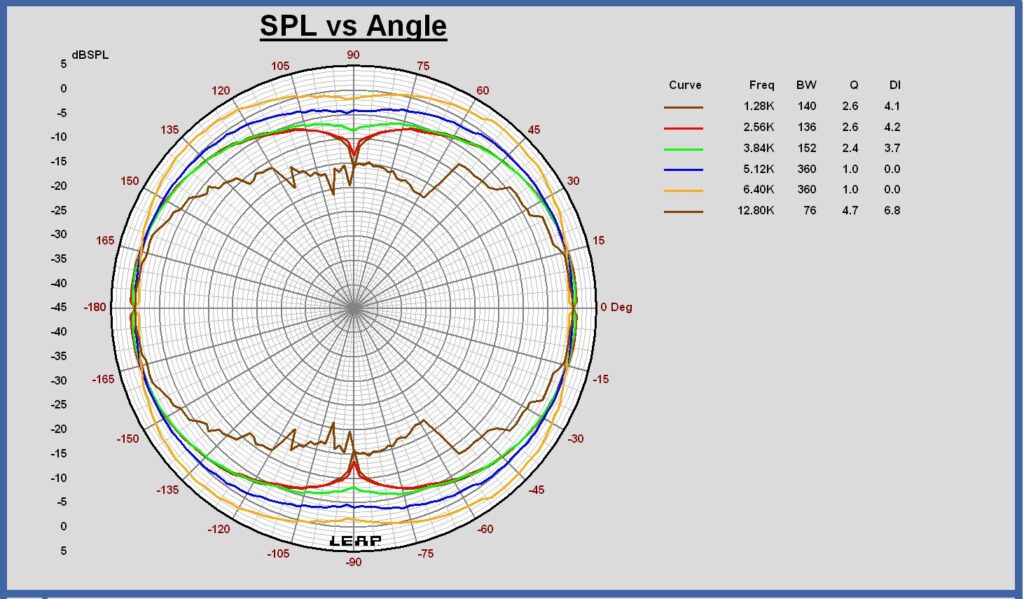
SPL on axis and vertical off axis 15 30 45 60 75 90 degrees at 3m, 2.83 Vrms in full sphere

Vertical polar diagram 1280 – 2560 – 3840 – 5120 – 6400 – 12800 Hz at 3m in full sphere
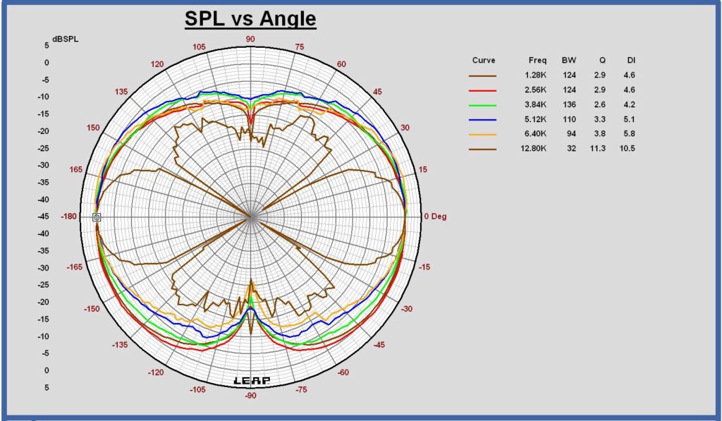
SPL on axis and the power at 3m, 2.83 Vrms in full sphere

Directivity Index at 3m in full sphere
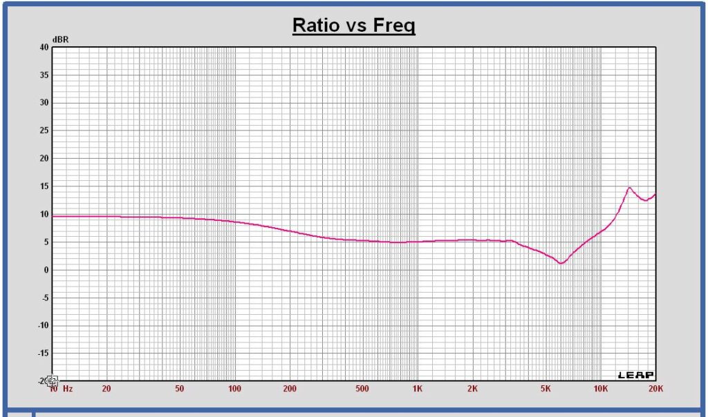
Remark: the deviation of the low frequency DI from 4.7 dB at low frequencies is caused by a Leap simulation artifact of the SPL at low frequencies.
Active Digital Crossover filter
A Linkwitz-Riley 4th order crossover filter is designed. To realize flat curves for SPL, power and directivity index and to realize the best overall dipole behavior versus frequency, the crossover frequencies are chosen at 250 and 2500 Hz.
The crossover filter is designed using analog functional blocks which are transformed to digital biquads that are programmed in miniDSP.
Crossover filter targets LR4 at 250 and 2500 Hz
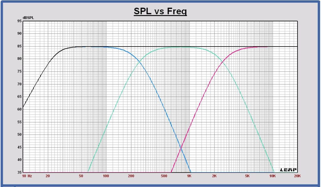
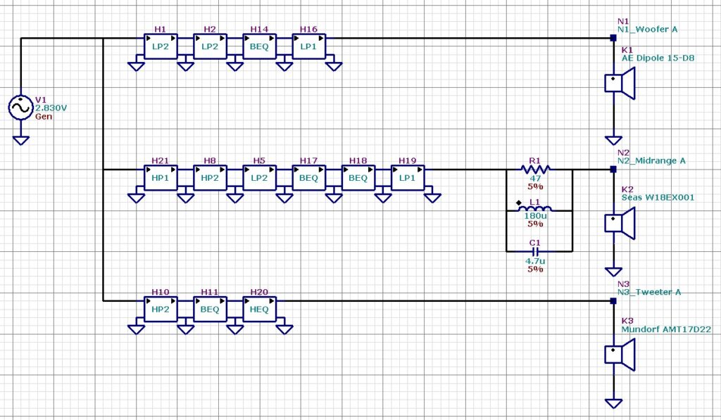
Crossover filter schematic with functional blocks
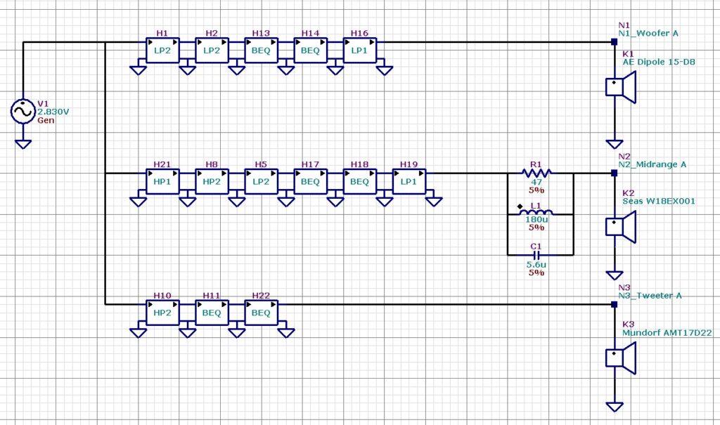
woofer filter: 5 blocks; midrange filter: 6 blocks; tweeter filter: 3 blocks.
The number of digital biquads is the same.
A parallel RLC circuit is added in series with the midrange to reduce the third harmonic distortion caused by the break up resonance peak at 5 kHz.
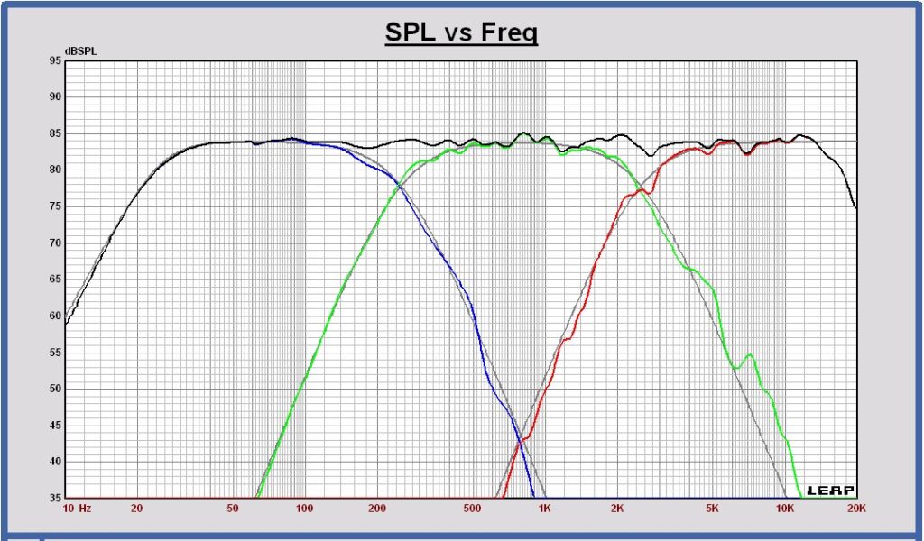
SPL on axis of the filtered drivers and the sum at 1m, 2.83 Vrms in full space
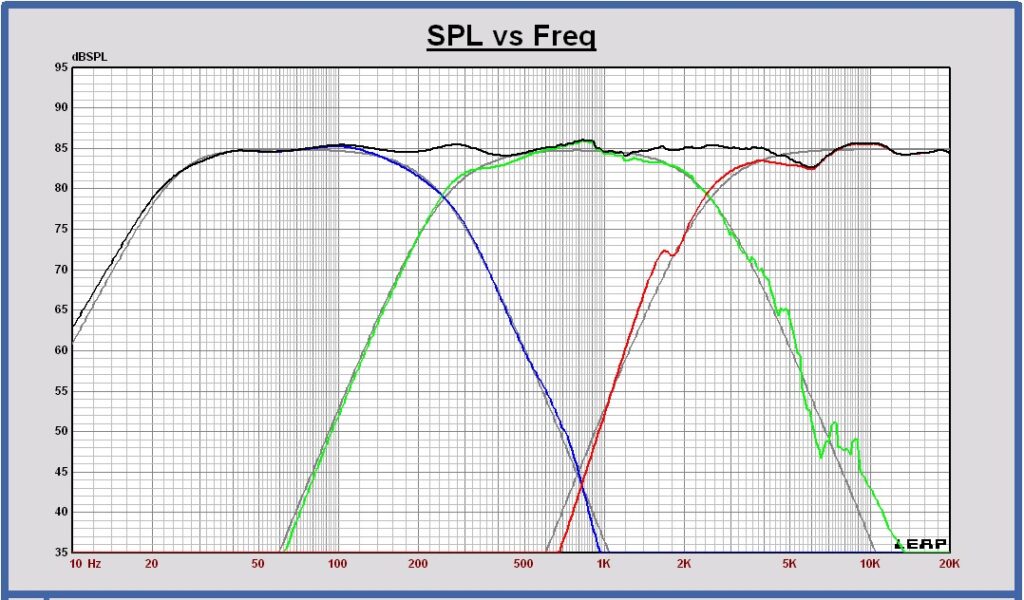
SPL horizontal off axis of the sum at 0 , 15, 30, 45 and 60 degrees at 3m, 2.83 Vrms
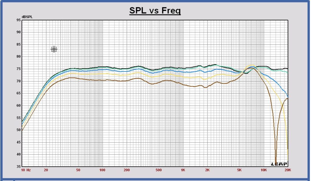
Power response of the filtered drivers and the sum in free space at 3m, 2.83 Vrms in full space
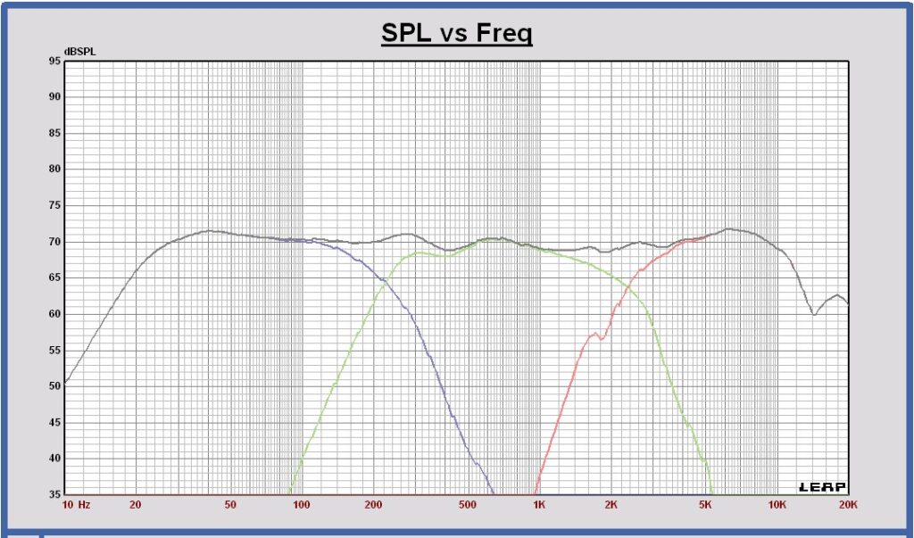
Directivity Index in free space of the filtered drivers and the sum
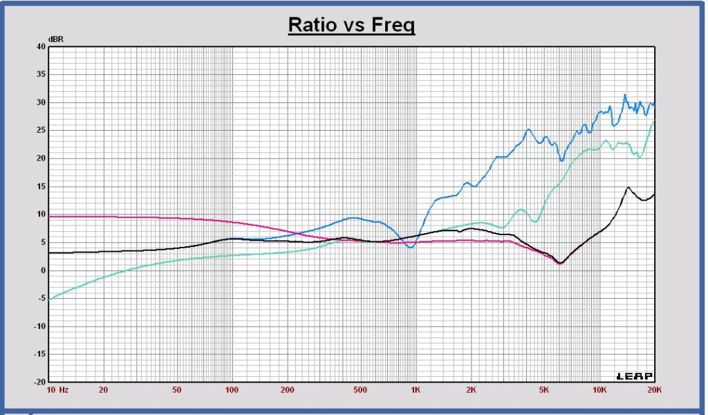
The total DI curve shows that this loudspeaker has a dipole radiation behavior up to about 5 kHz. Around 6 kHz there is a DI dip due to a more omnidirectional behavior of the tweeter. Between 300 and 4000 Hz the DI is higher than the theorical dipole DI value of 4.5 dB. It is caused by some beaming caused by the transducer baffles. The DI deviation is reduced to a minimum by choosing the baffles as small as possible for each transducer.
Maximum excursion and maximum SPL with crossover filter
Maximum excursion
With the designed Linkwitz – Riley 4th order filter, the woofer has a maximum excursion of 15 mm peak at 25 Hz for a voltage of 11.3 Vrms at the input of the filter.
The excursion of the midrange and the tweeter have been calculated also at 11.3 Vrms.
Excursion peak at 11.3 Vrms of woofer (blue), midrange (green) and tweeter (red)
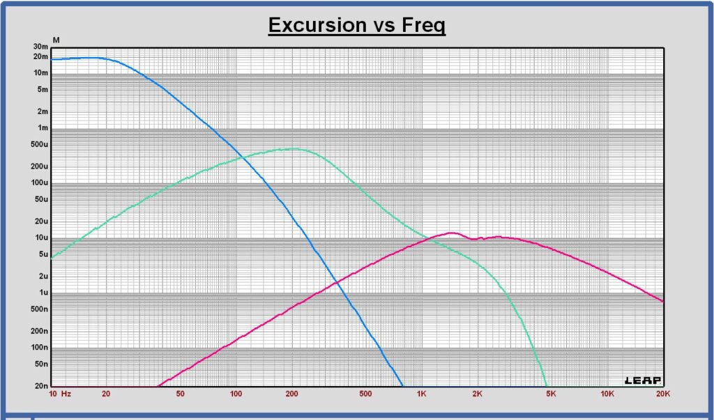
The midrange excursion is maximum at 206 Hz and equal to 0.428 mm peak.
The maximum specified linear excursion of the Seas W18EX001 is 5 mm peak.
The tweeter excursion is maximum at 1443 Hz and equal to 0.012 mm peak.
The maximum linear excursion of the Mundorf AMT17D2.2 is not specified.
Maximum SPL
At maximum excursion of the woofer at 25 Hz, the maximum SPL for the operating frequency range 25 – 20000 Hz, is 98 dB at 1m and 11.3 Vrms at the input of the crossover filter.
On axis ground plane measurements
Ward did some indoor ground plane measurements of his dipole speakers. Using the measured SPL results of the individual transducers, the digital crossover has been updated to a more accurate design. With the new filter the sound is a lot better, even very good now.
Ward will also measure the off axis SPL responses of the individual transducers soon. Then, more correct curves of the power and the directiviy index can be calculated and used for a further optimization of the design.
Measurement setup
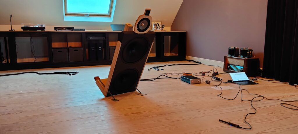
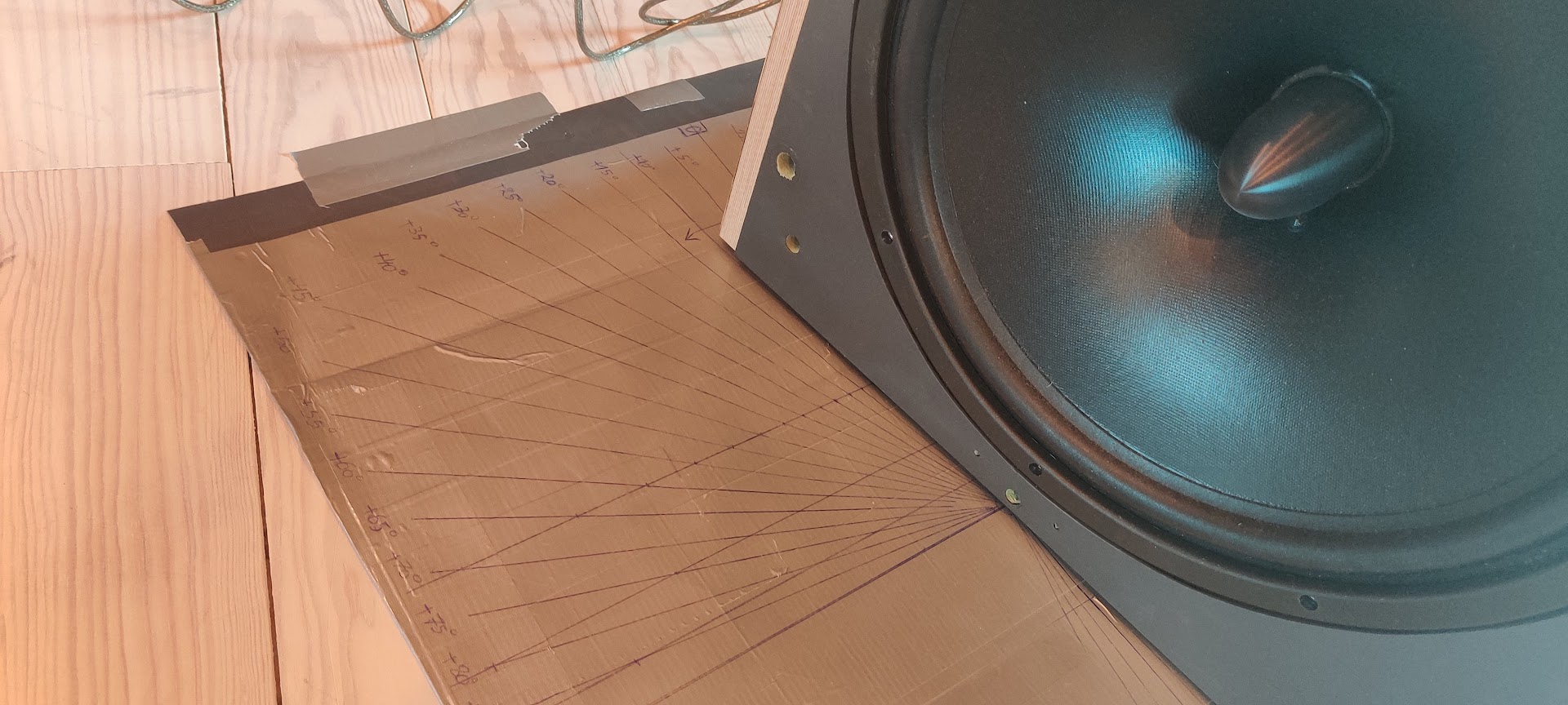
The speaker baffle is tilted in a way that for each transducer measurement the microphone is located at exactly 2 m distance from the front baffle at each transducer vertical position on the baffle, on axis of the woofers, the midrange or the tweeter.
Remark that the SPL of a ground plane measurement at 2m distance is 6 dB higher than a full space measurement at 2m. That means that the SPL of a ground plane measurement at 2 m is equal to a full space measurement at 1m.
Woofer ground plane measurements
Measured SPL of the woofers at 2m, 2.83 Vrms ground plane (equal to 1m full space) in blue color
SPL of the woofers on infinite baffle at 1m, 2.83 Vrms in pink color
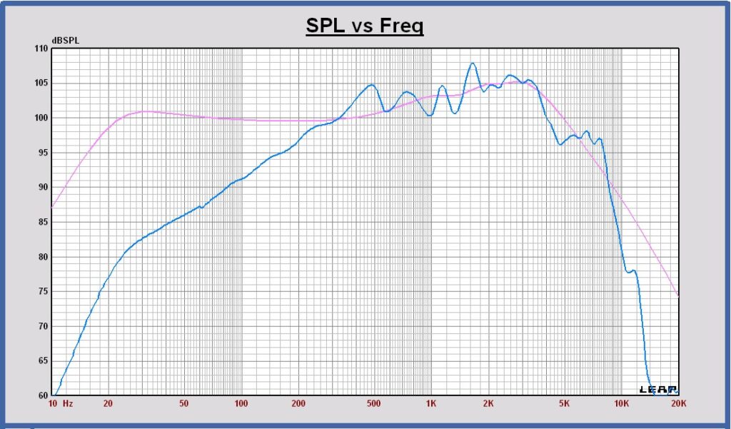
Measured woofer impulse response
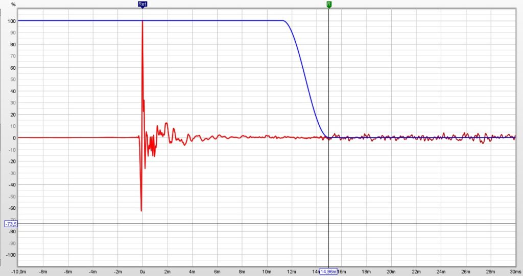
The FFT measurment window can be chosen at 15 ms. It means the measurements are free of high level reflections down to 65 Hz.
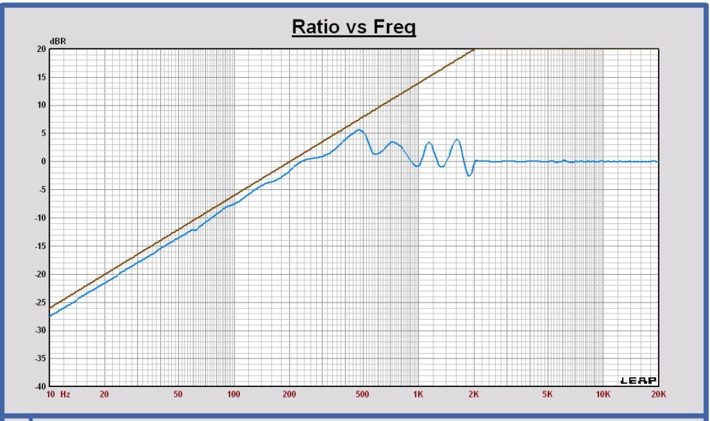
At lower frequencies below 65 Hz a SPL correction is calculated in a way the dipole transfer of the woofers in their open baffle is equal to a + 6dB transfer function at low frequencies. The dipole transfer is the ratio of the SPL in the open baffle in full space over the SPL on infinite baffle.
As the infinite baffle can be accurately calculated using the measured TSP and the + 6 dB transfer is well defined also, the SPL of the dipole in full space can be exactly calculated to its correct value at low frequencies.
Woofer dipole transfer after correction of the SPL in full space in blue and the + 6 dB transfer in brown
Midrange ground plane measurements
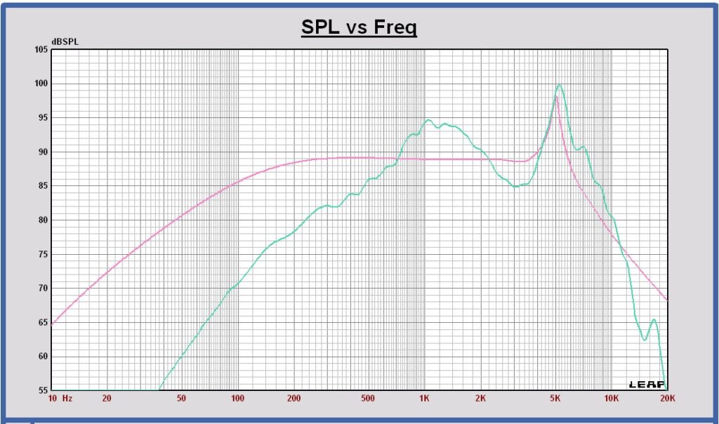
Measured SPL of the midrange at 2m, 2.83 Vrms ground plane (equal to 1m full space) in green color
SPL of the midrange on infinite baffle at 1m, 2.83 Vrms in pink color
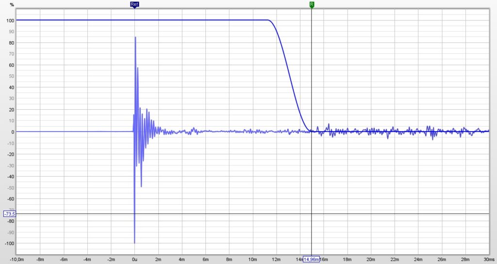
Measured midrange impulse response
Midrange dipole transfer after correction of the SPL in full space in green and the + 6 dB transfer in brown
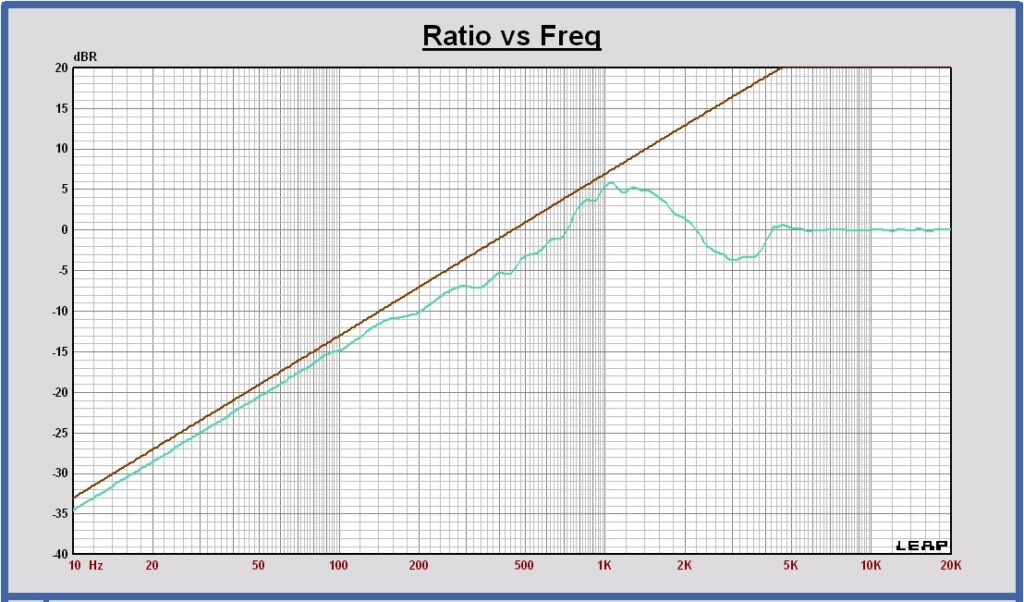
The same low frequency SPL correction, as described for the woofer dipole, is also done for the midrange SPL dipole response.
Tweeter ground plane measurements
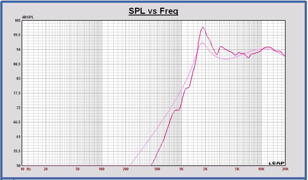
Measured SPL of the tweeter at 2m, 2.83 Vrms ground plane (equal to 1m full space) in red color
SPL of the tweeter on infinite baffle at 1m, 2.83 Vrms in pink color
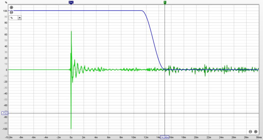
Measured tweeter impulse response
Tweeter dipole transfer after correction of the SPL in full space in red and the + 6 dB transfer in brown
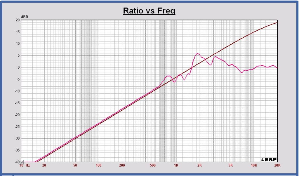
The same low frequency SPL correction, as described for the woofer dipole, is also done for the tweeter SPL dipole response.
Off axis ground plane and free space measurements
Woofers horizontal off axis ground plane measurements
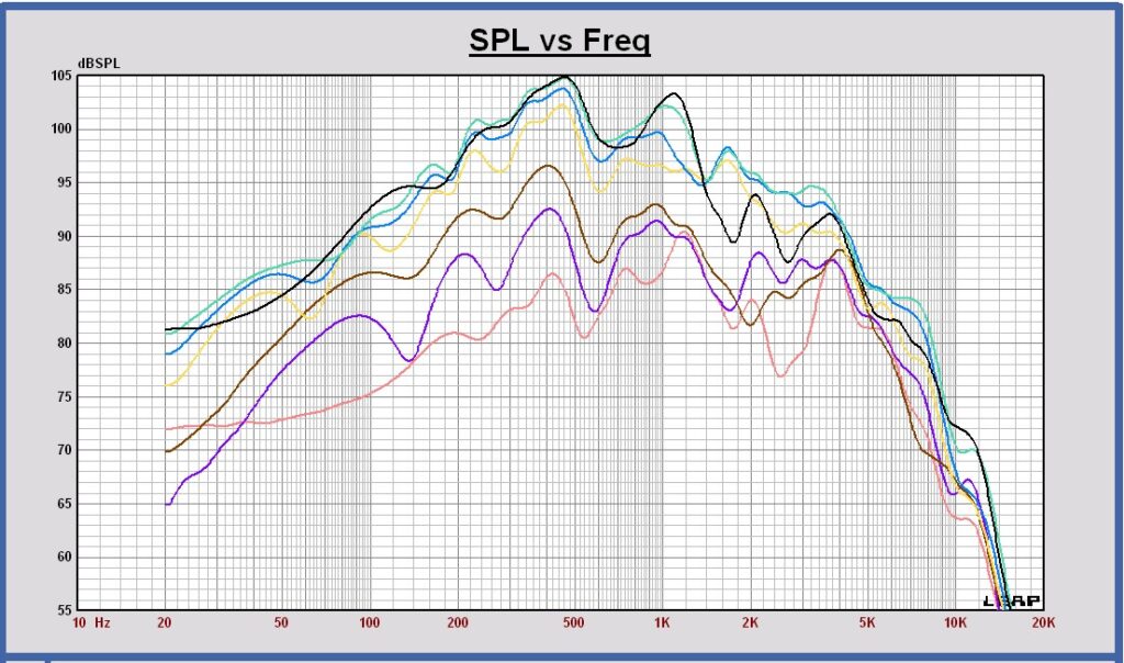
The off axis woofers SPL curves are measured with a ground plane measurement at 3 m distance. The baffle is placed perpendicular to the ground, in a way the vertical off axis angle is – 8.5 degrees and not 0 degrees. The SPL deviation is minimal with this vertical angle offset. The SPL curves can be used to evaluate the SPL off axis behavior and to calculate the power response and the directivity index.
Measured horizontal off axis SPL of the woofers at 3m, 2.83 Vrms ground plane (levels re-calculated to 1m full space)
at 0, 15, 30, 45, 60, 75 and 90 degrees
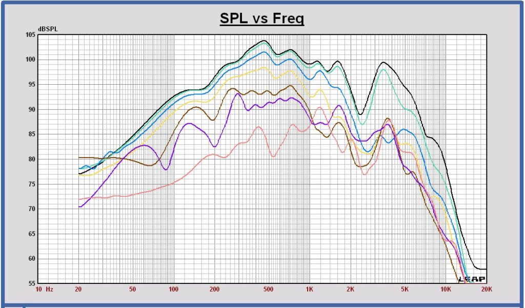
Measured horizontal off axis SPL of the woofers at 3m, 2.83 Vrms ground plane (levels re-calculated to 1m full space)
at 180, 165, 150, 135, 120, 105, and 90 degrees
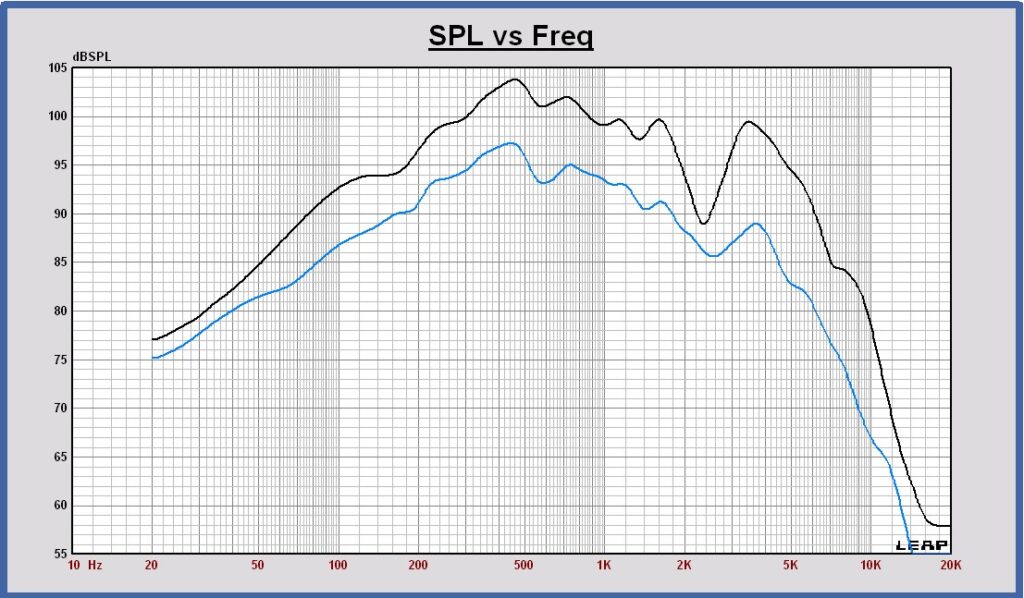
Measured woofers SPL on axis (black) and the power (blue) at 1m, 2.83 Vrms in full space.
Power calculated with the woofers horizontal off axis measurements only.
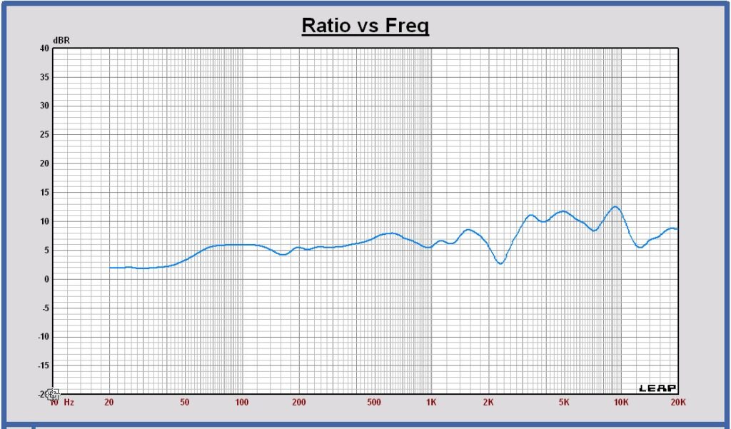
Directivity Index of the woofers in full space, calculated with the woofers horizontal off axis measurements only
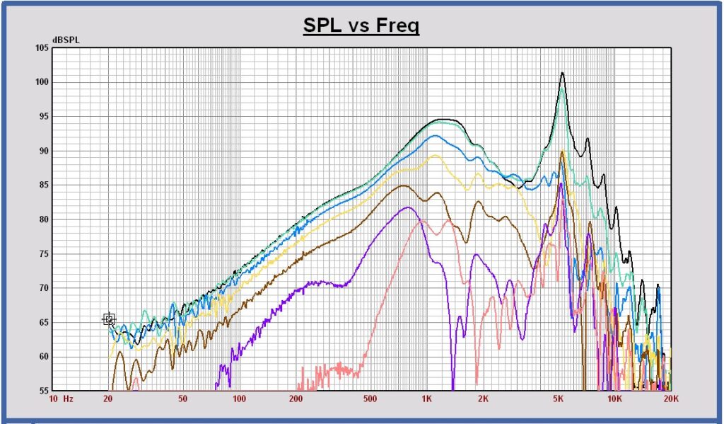
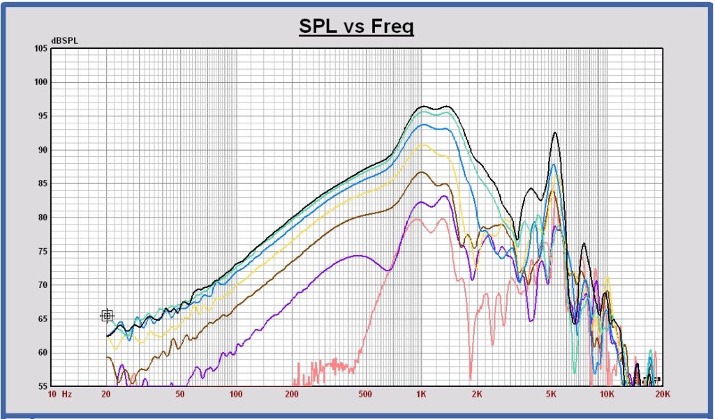
Midrange horizontal off axis free space measurements
The off axis midrange SPL curves are measured with a free space measurement at 1 m distance.
Measured horizontal off axis SPL of the midrange at 1m, 2.83 Vrms in full space
at 0, 15, 30, 45, 60, 75 and 90 degrees
Measured horizontal off axis SPL of the midrange at 1m, 2.83 Vrms full space
at 180, 165, 150, 135, 120, 105, and 90 degrees
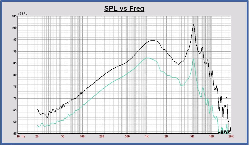
Measured midrange SPL on axis (black) and the power (green) at 1m, 2.83 Vrms in full space.
Power calculated with the midrange horizontal off axis measurements only.
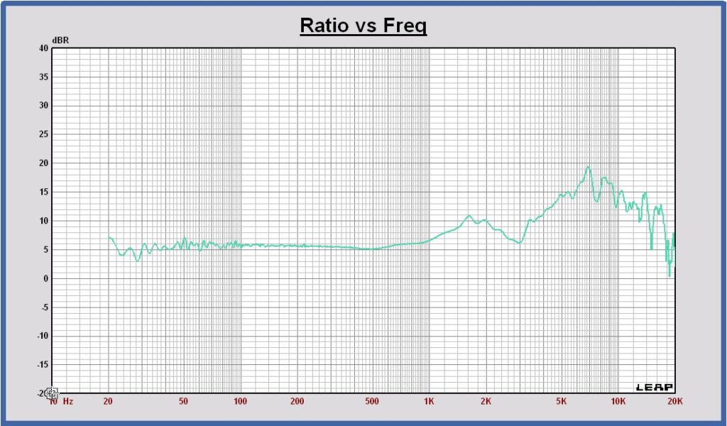
Directivity Index of the midrange in full space, calculated with the midrange horizontal off axis measurements only
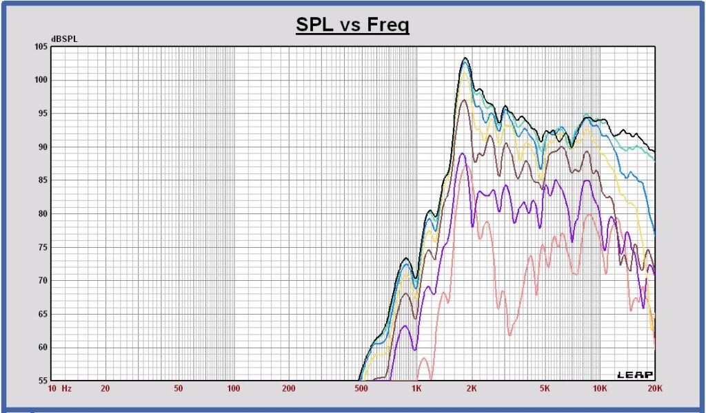
Tweeter horizontal off axis free space measurements
The off axis tweeter SPL curves are measured with a free space measurement at 1 m distance.
Measured horizontal off axis SPL of the tweeter at 1m, 2.83 Vrms in full space
at 0, 15, 30, 45, 60, 75 and 90 degrees
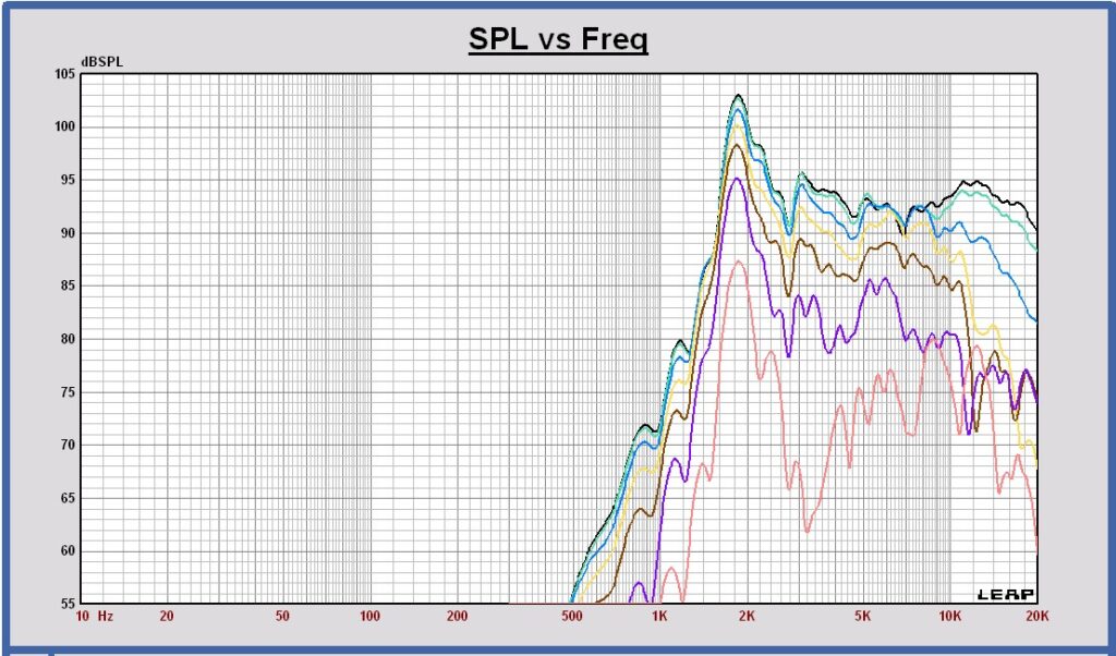
Measured horizontal off axis SPL of the tweeter at 1m, 2.83 Vrms full space
at 180, 165, 150, 135, 120, 105, and 90 degrees
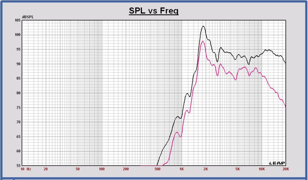
Measured tweeter SPL on axis (black) and the power (red) at 1m, 2.83 Vrms in full space.
Power calculated with the tweeter horizontal off axis measurements only.
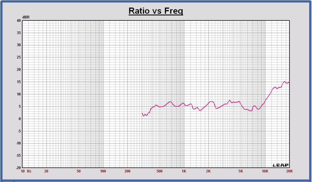
Directivity Index of the tweeter in full space, calculated with the tweeter horizontal off axis measurements only
All transducers
Directivity Index of the woofer (blue), the midrange (green) and the tweeter (red) in full space, calculated with the horizontal off axis measurements of the tranducers only
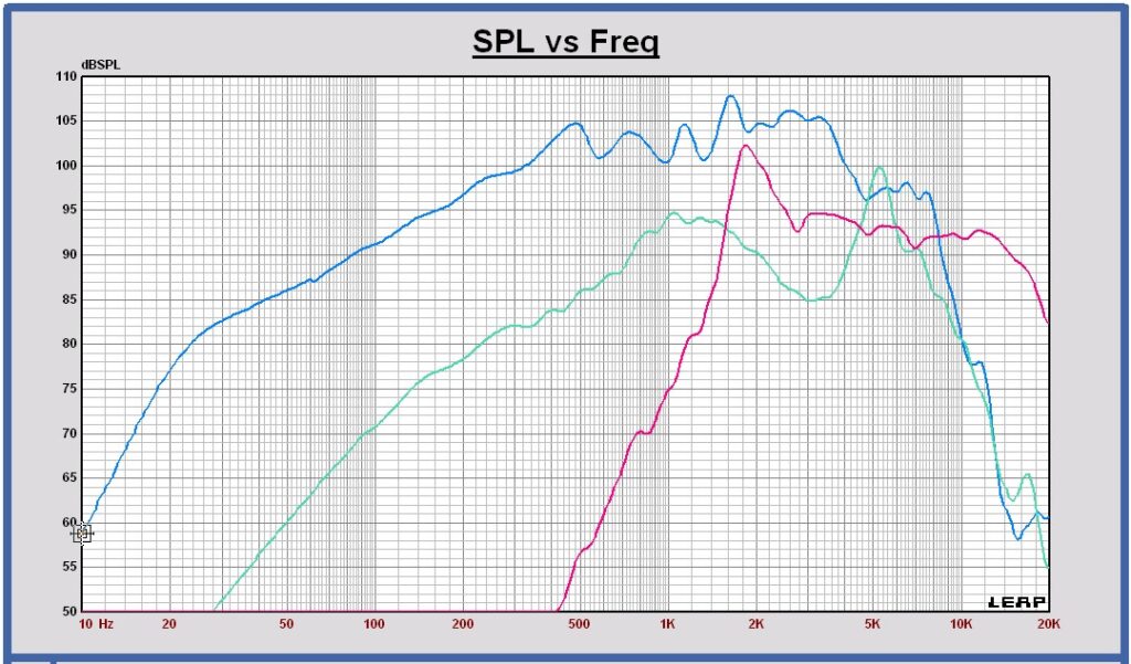
Update Active Digital Filter using SPL measurements
SPL measurements of woofer, midrange and tweeter at 2m, 2.83 Vrms ground plane (equal to full space at 1m)
Crossover filter schematic with functional blocks
SPL on axis of the filtered drivers and the sum at 1m, 2.83 Vrms in full space
SPL horizontal off axis of the sum at 0 , 15, 30, 45 and 60 degrees at 3m, 2.83 Vrms
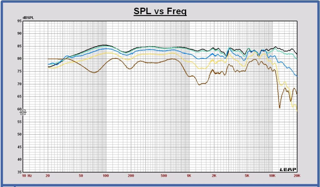
Power response of the filtered drivers and the sum in free space at 3m, 2.83 Vrms in full space
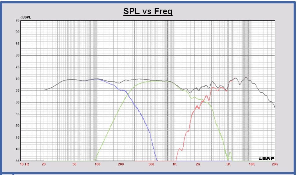
Directivity Index in free space of the filtered drivers and the sum

Some conclusions about the speaker design
As can be seen in the total power curve of the speaker, there is a power dip around 1500 Hz, even more than expected in the simulations. With the current midrange frame and baffle dimensions, the dipole behavior becomes poor above 1 kHz. The dipole peak is located around 1500 Hz and the dipole notch at 3 kHz. As a consequence the directivity index of the midrange increases above 1 kHz to a maximum at 1500 Hz and a minimum at 3000 Hz. At high frequencies the directivity index is limited by the beaming of the midrange itself. This power behavior can be improved by decreasing the midrange outside dimensions. The baffle size can be reduced further to a minimum equal to the frame dimensions. A smaller midrange is a possible alternative too.
Harmonic distortion improvement of the midrange transducer
The harmonic distortion of the midrange transducer is measured, connecting a 1 Vrms sine wave to the voice coil terminals.
A 3rd harmonic distortion peak at 1.73 kHz can be observed. This harmonic component is located exactly at the cone breakup resonance frequency of 5.21 kHz and the 3rd harmonic distortion will become high.
Seas W18EX001 harmonic distortion @ 1 Vrms voltage directly on the voice coil terminals
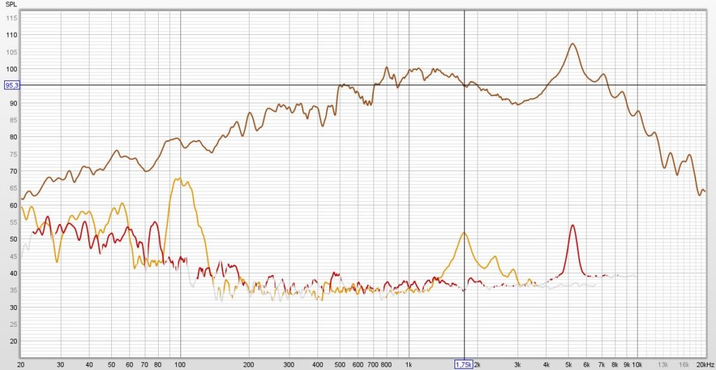
The 3rd harmonic distortion peak at 1.73 kHz is -43 dB.
Distortion improvement
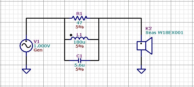
The distortion can be reduced by placing a parallel RLC circuit, tuned at the resonance peak frequency of 5.21 kHz between the voltage source and the voice coil terminals. Because the source impedance is increased by adding the RLC circuit, the 3rd harmonic distortion current at the resonance frequency will decrease.
Some notch filtering applied in DSP or with an analog filter on the voltage of the source at the resonance frequency of 5.21 kHz, will not reduce the distortion. The voltage source impedance will stay low and the distortion current at the resonance frequency will not decrease.
The distortion peaks caused by the other resonance frequencies above 5.21 kHz of this midrange transducer are not reduced by this single RLC circuit.
Seas W18EX001 harmonic distortion @ 1 Vrms voltage on the voice coil terminals via the RLC circuit
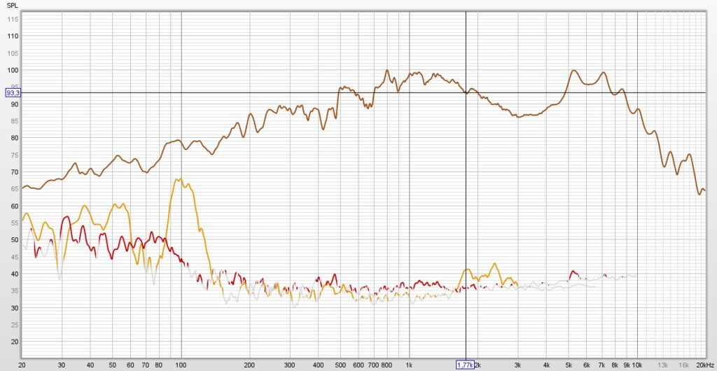
The 3rd harmonic distortion peak at 1.73 kHz is now -52 dB. That is 9 dB better.
The amount of the distortion reduction is the same as the resonance peak attenuation caused by the parallel RLC circuit.
Gallery
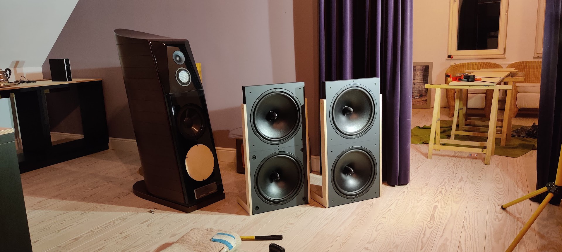
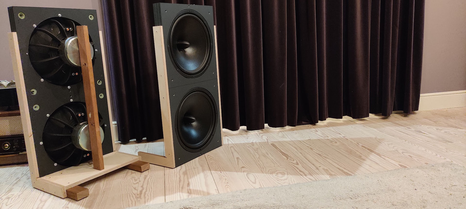
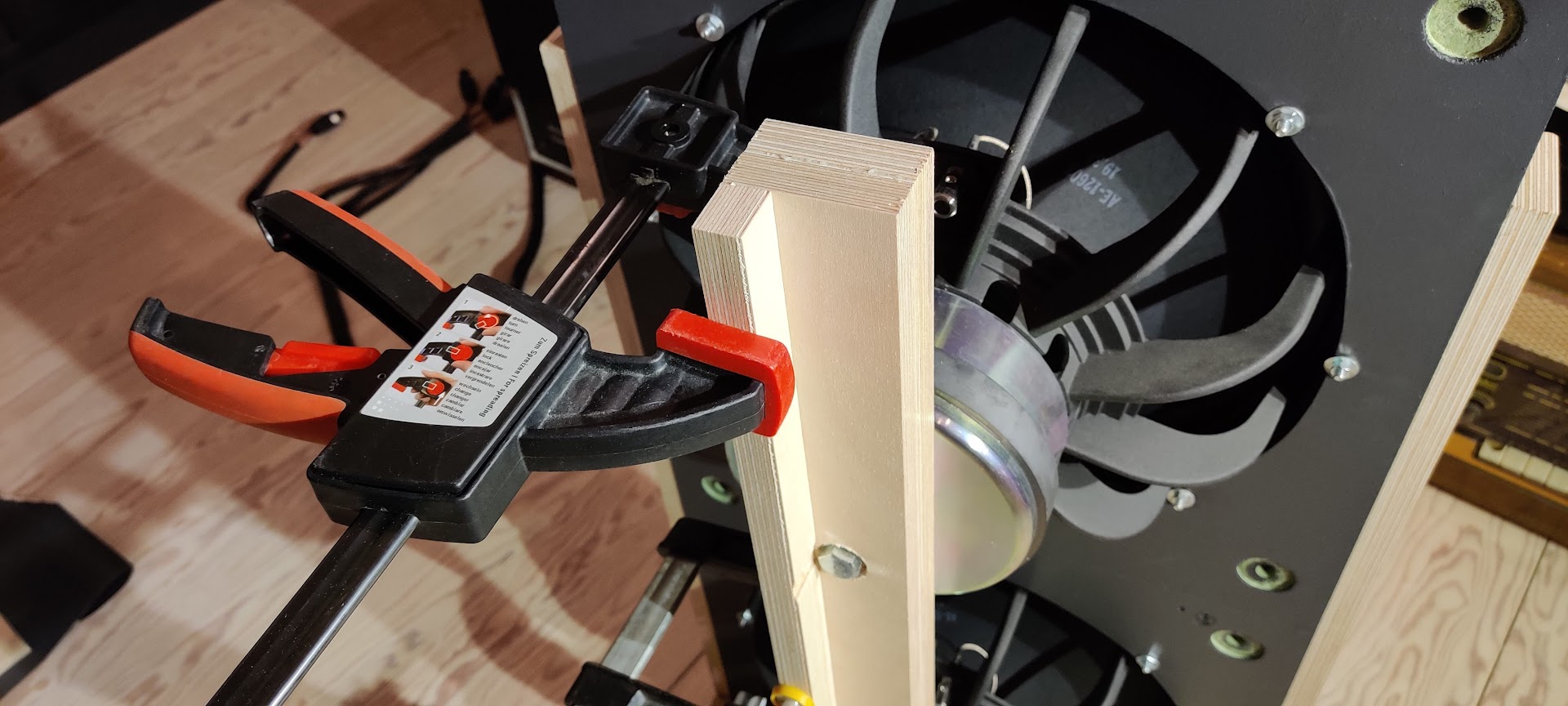
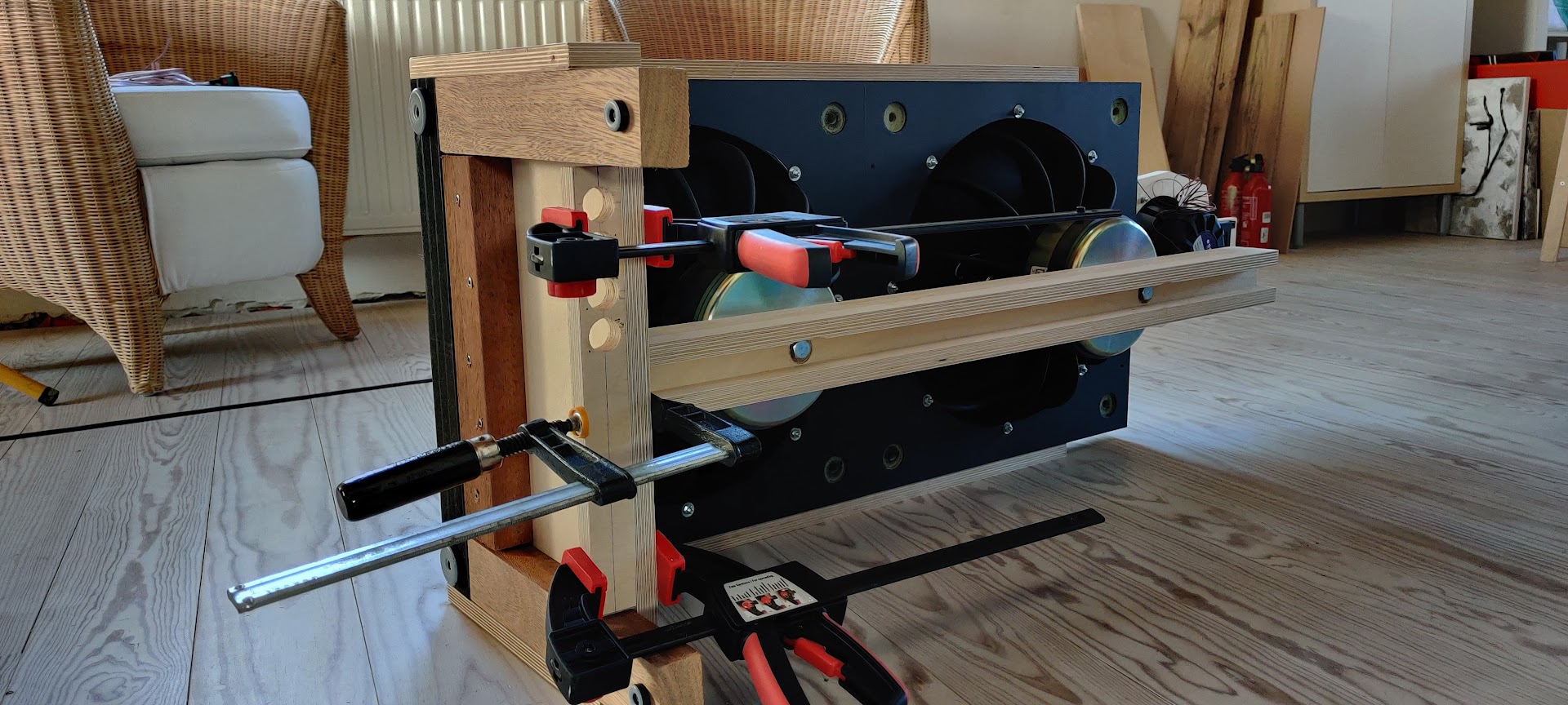
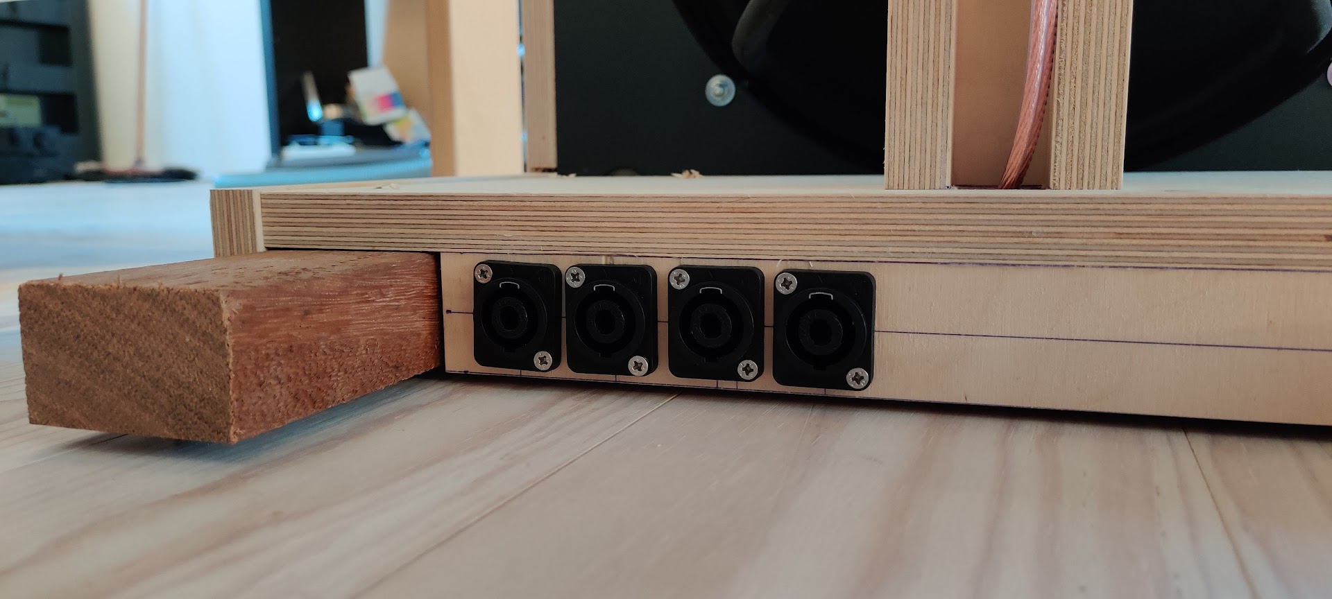
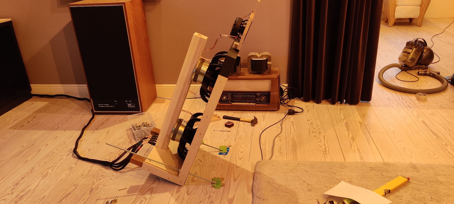
Speaker buiding
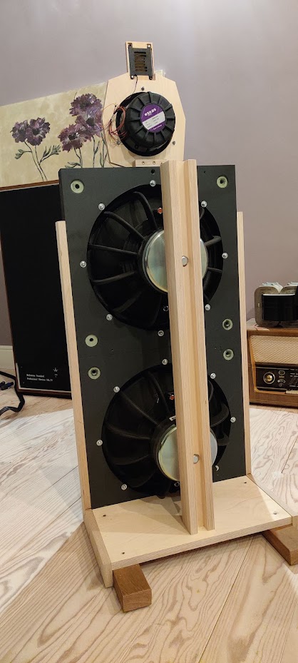
Speakers ready
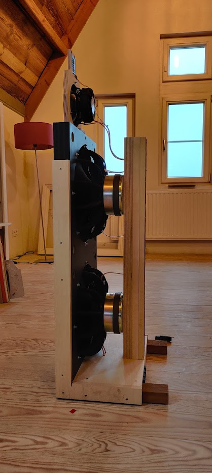
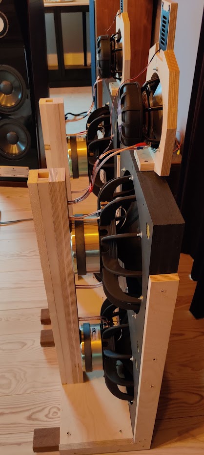
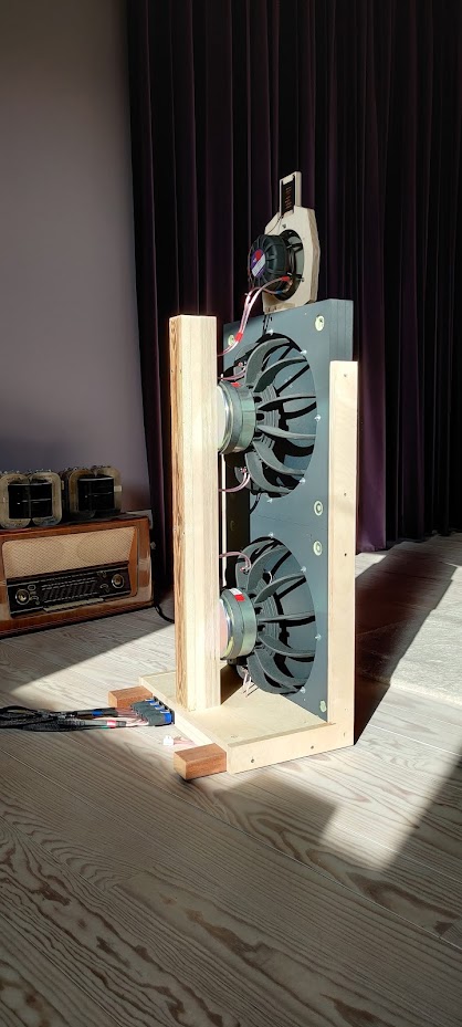

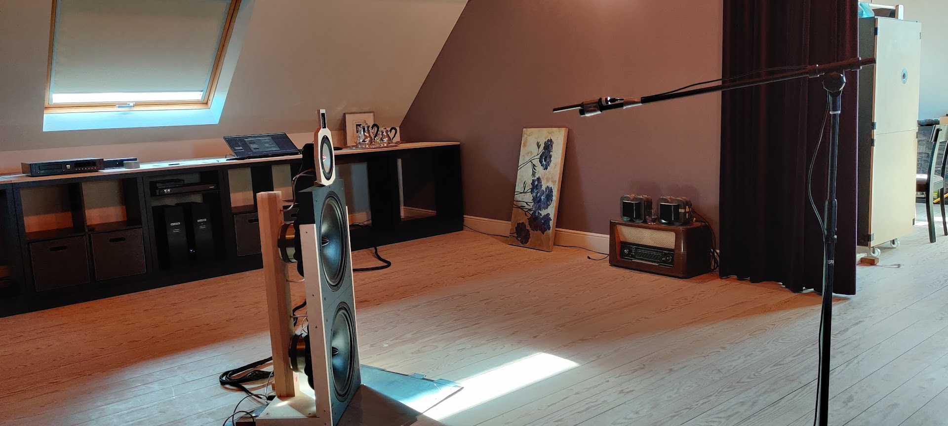
Acoustical measurement setup
Listening room
Listening
Ward’s experiences, after listening some time to the speaker with the final filter design.
”And now the million dollar question, how does it sound?
The speakers simply sound great to my ears. However, I need to address that I only express my personal opinion which can differ quite substantially from the opinion of other respectable listeners.
Most reviews of big high end speakers often emphasize on the fact that the speakers can deliver an enormous soundstage with an insane amount of sound pressure at the lowest possible distortion level. All numbers are maximized or minimized. I can tell you that the VCLLABS DI-215/W prototype speaker is able to deliver this too. It has a -3dB of 25 Hz low cutoff point, it can play very loud and your ears will distort before the speakers will do so. However, the speakers do much more than this. Most big, expensive speakers are able to impress when playing a series of well selected demo tracks. That is a very convincing selling argument ! During a typical demo, sound levels are way too high and ‘easy’ music is used to seduce the audience. However, in most cases, the speaker will disappoint when listening to ‘normal’ music tracks at reasonable sound levels. And that’s where the dipole speaker makes a real difference. Even at low levels, you hear a kind of transparency that is normally not heard. That’s also the main reason that you do not need to push the levels to be involved in the music. The music comes to you and grabs your attention. The lower frequencies are exciting because they are not influenced by spurious delayed panel resonances of the cabinet or standing waves in the room. That’s the reason you can actually hear 25 Hz notes with this speaker as these notes are not blurred by masking signals.
The midrange offers the speaker it’s magical touch, the delicacy that you can expect from dipole operation. Of course, many different options are still available to experiment and tailor the sound to your personal liking.
The high frequencies are nothing short of true magic due to the use of the very small Heil motion from Mundorf.
At last we come to the spatial representation, the 3D image that is thrown in the room. This is also very good and can be very convincing with razor sharp delineation of the individual,acoustic spaces. However, it is quite different from what can be expected from a normal monopole speaker setup which throws a very broad 3-D picture in the room. The dipoles rather deliver a more narrow but very deep soundstage. In the dark, it can be very convincing and sometimes even creepy, but sometimes, I wished that the large 3D sonic picture of my conventional setup would appear in front of me. Also, the dipole has less tendency of filling the room with sound which is quite normal because it pumps less acoustic power into the room. As a consequence the expected stereo experience is more restricted to a one seater situation. When it comes to dynamics and with this term I mean dynamic contrast, the difference between silent and loud passages, the speaker is simply stunning. It can surprise you in the same way as experienced in a concert hall as you are entertained by the musical performance of the artists. Instruments that stand out in particular are violin, trumpet and harpsichord. The speakers are able to recreate the complex acoustic sonority of these instruments that is heard during a live performance. This might be the strongest aspect of the dipole concept. They make a copy of the musical event.“

