Transducer electro-mechanical model
- General
- Electro-mechanical schematic
- Equation of motion
- Displacement versus frequency
- Acceleration versus frequency
- Example
- Current source connected to transducer coil
General
This study is about the electro-mechanical behavior of a loudspeaker transducer. The acoustical behavior is not explained yet. The electro-mechanical behavior will be explained in terms of displacement, velocity and acceleration.
Electro-mechanical schematic

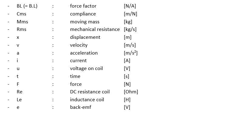
A coil with a moving mass Mms and a suspension with a compliance Cms and mechanical resistance Rms, is connected to a voltage source u. The coil has a length L and is positioned in a magnetic field with induction B. A current i will flow and the coil will move in the magnetic field.
Parameters
Electrical equivalent schematic
Voltage steering of the coil will be considered. To calculate the current i, the electrical equivalent schematic has to be considered.

Conform Lenz’s Law, a back-emf voltage E appears across the coil if it is moving in a magnetic field.
Back-emf e = B . L . v
Equation of motion
Applied force F = BL . i
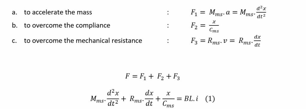
For the frequency range of interest, lower than 1 kHz, Le can be assumed to be zero in the electrical equivalent schematic.
Then:

Out of equation (1) and (2), the equation of motion (3) can be calculated:

If the equation of motion is solved in the time domain, the displacement of the transducer as a function of time can be calculated. Time responses like impulse, step and steady state responses can be calculated.
Displacement versus frequency
To examine the frequency response of the transducer voice coil motion, the equation of motion that is calculated in the time domain, must be transformed to the frequency domain via the Laplace transform.
The Laplace transform of Equation (3) is:

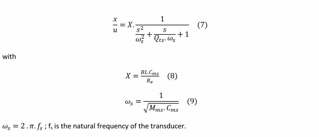
The displacement transfer x/u as a function of frequency is:

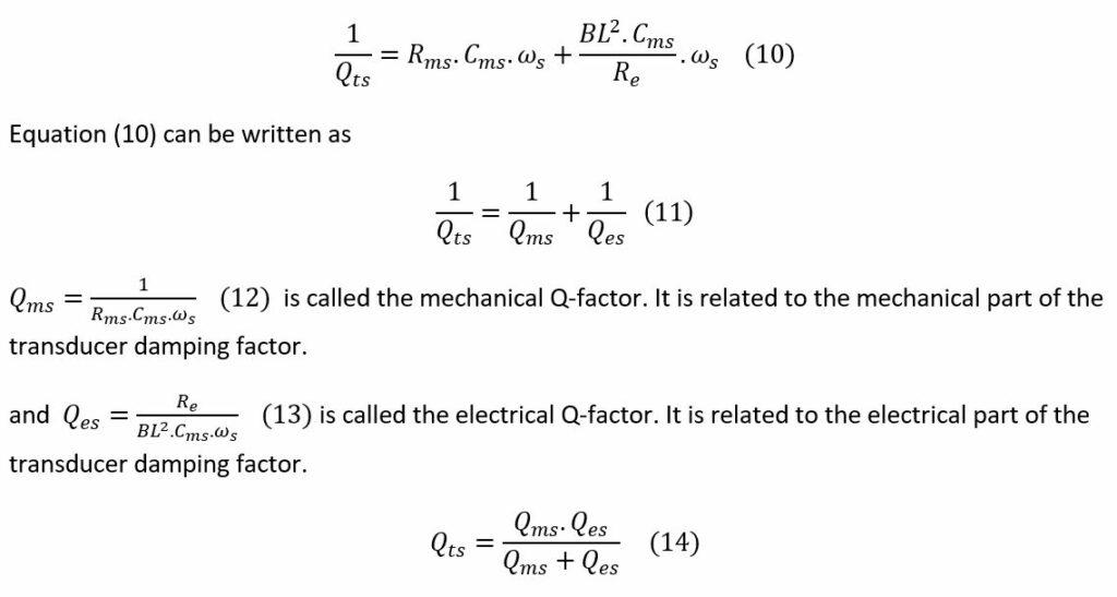
The displacement transfer x/u of equation (5) can be written as a general form of a second order transfer function:
Acceleration versus frequency
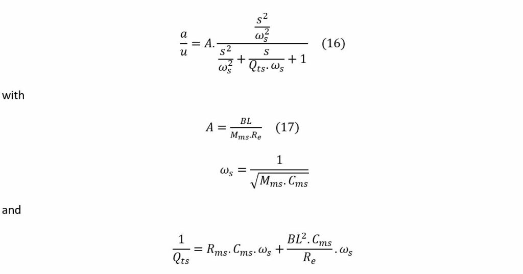
The acceleration transfer a/u as a function of frequency is:

The acceleration transfer a/u of equation (6) can be written as a general form of a second order transfer function:
Example
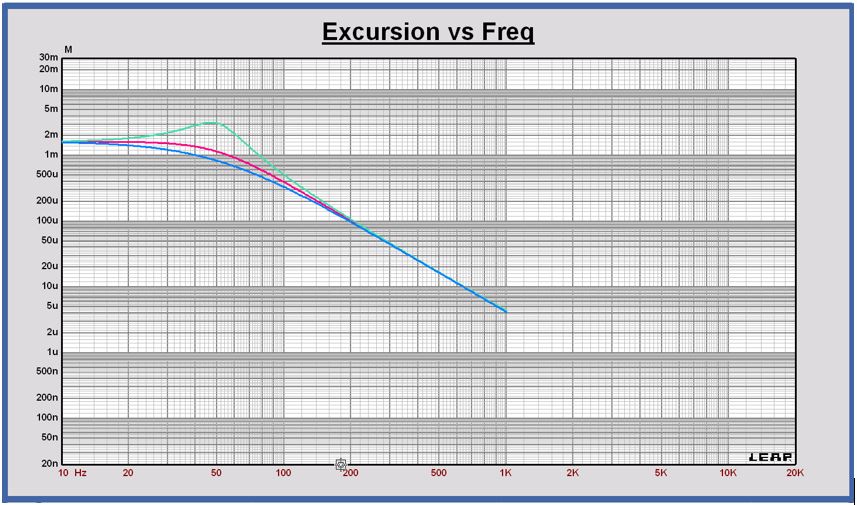
Parameters of a transducer example:

For these parameter values fs = 50 Hz and Qts = 0.70.
Displacement as a function of frequency @ u = 2.83 Vrms
In red color: the displacement of the example.
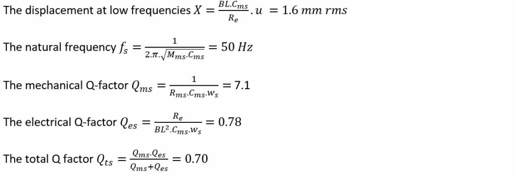
The displacement of the transducer is a low pass second order function at the frequency fs with a Q-factor Qts.
To illustrate the impact of the Q-factor value, the green curve is the displacement for a transducer with Qts = 2.0 and the blue curve for a transducer with Qts = 0.50.
Acceleration as a function of frequency @ u = 2.83 Vrms
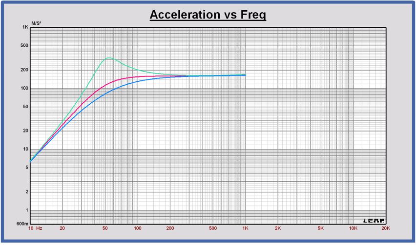
In red color: the acceleration of the example.

The displacement of the transducer is a high pass second order function at the frequency fs with a Q-factor Qts.
To illustrate the impact of the Q-factor value, the green curve is the acceleration for a transducer with Qts = 2.0 and the blue curve for a transducer with Qts = 0.50.
Current source connected to the transducer coil
If the transducer coil is connected to a current source, the current i will not be determined by the back-emf e. As a consequence there is no damping caused by the back-emf voltage. The displacement and acceleration will become second order functions at the natural frequency fs and a total Q-factor Qts equal to the mechanical Q-factor Qms. There is no electrical damping with the current source configuration.
