Loudspeaker Domain Spaces

Loudspeaker enclosures can be considered and simulated in different types of acoustic domains.
Infinite Baffle, Full Space and Half Space are frequently used in loudspeaker design.
The differences between these domains are defined by their boundary reflections, and in most cases the restricted locations of the transducer. The response of the enclosure will change when simulated or measured in the various domains.
Contents
Infinite Baffle
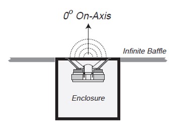
In this domain the transducer or the enclosure is recessed into an infinite baffle with the front baffle board flush with the plane. Radiation is only produced into a half space (2π) field in front of the plane, as shown in Figure 1.
Since the sides and the rear of the enclosure are outside the radiation filed, there is no diffraction at the enclosure boundaries.
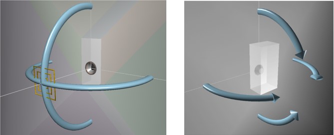
The 3D layout in Figure 2 shows the setup both from the front and rear. The baffle board of the enclosure is fixed in the plane of the infinite baffle, with the rest of the enclosure shown behind it.
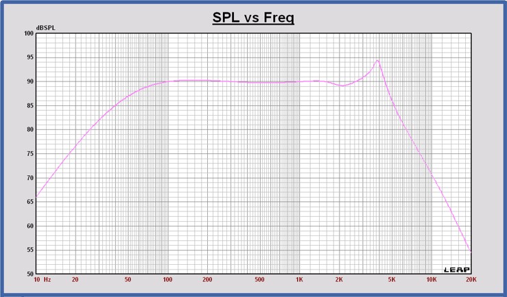
The graph in Figure 3 demonstrates the response of the Scanspeak 26W8531G00 transducer mounted in the VCL EM2 loudspeaker enclosure of 55 liters simulated in the Infinite Baffle domain.
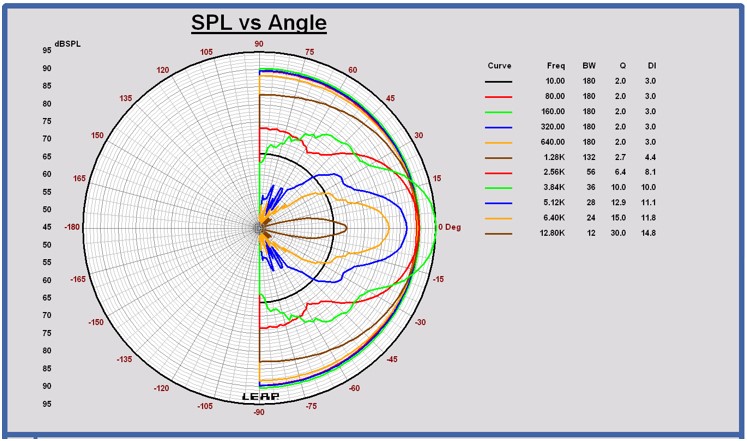
The horizontal and vertical polar patterns in Figure 4 would be identical, since there is only a single transducer in this example. Moreover, acoustic response is only produced in the front half of the domain between ±90 degrees
Full Space
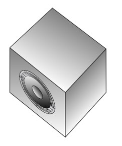
In this domain the enclosure has no boundaries surrounding it whatsoever. Radiation is produced into a full space (4π) field in all directions. This domain is often described as anechoic since there are no reflections from any direction. Since all sides of the enclosure are within the radiation field, diffraction takes place around the entire shell of the enclosure.
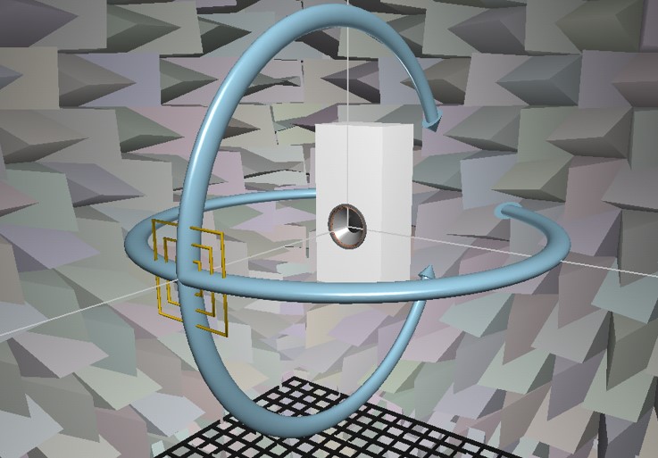
The 3D Layout in Figure 6 shows this domain in the context of an anechoic chamber, as indicated by the room walls covered with wedges. This provides realistic visualization and optical reflection for the enclosure surfaces, rather than an empty white background.
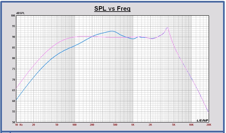
The graph in Figure 7 shows the on-axis response for both the Full Space simulation (blue color) as well as the previous Infinite Baffle simulation (pink color). Above 1kHz there is little difference in the response. At these high frequencies the transducer itself becomes directional and the changes between the domains are irrelevant.
Note that at 450Hz there is a rise or bump in the response. This is where the directivity of the enclosure itself begins to act as a baffle, causing the response to approach the same and even higher levels as seen in the Infinite Baffle simulation. The shape, size, and location of the transducers on the enclosure will control the response in this region.
However, at lower frequencies there is now a substantial reduction in the Full Space response. The low frequency radiation is spreading out around the box into twice the available space.
Comparing these two simulations shows that the shape of the response curve is very much dependent on the environment. The relative level difference between low and high frequency regions are directly affected by the domain.
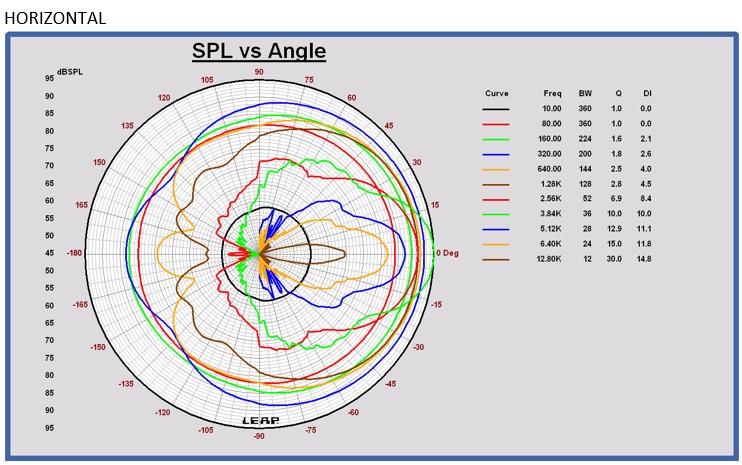
The horizontal and vertical polar graphs are shown in Figure 8 and Figure 9, for the Full Space domain. There is now radiation 360° around the enclosure. It is clear from these graphs that very little high frequency output appears behind the enclosure, while at low frequencies the response is very omnidirectional.
Half Space & Ground Plane
In this domain the enclosure has a single plane boundary similar to that of the Infinite Baffle, but here the enclosure is located over the plane, rather than recessed into it.
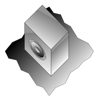
Radiation is produced into a half space (2π) field on a single side of the plane. Since the enclosure is within the radiation field, diffraction takes place around the entire shell of the enclosure. In general, the location of the simulation point ( or receiver) can be anywhere above the boundary plane.
However, a special configuration known as Ground Plane occurs when the receiver is located on the surface of the plane. Often the enclosure is angled towards the receiver location.
The two configurations are shown in Figure 11. In the general case with the receiver above the plane, multi-path radiation occurs caused by reflections from the plane. The result is cancellations or nulls in the response at certain frequencies.
In the ground plane layout there are no reflections since the receiver is on the boundary. These two configurations produce very different kinds of response.

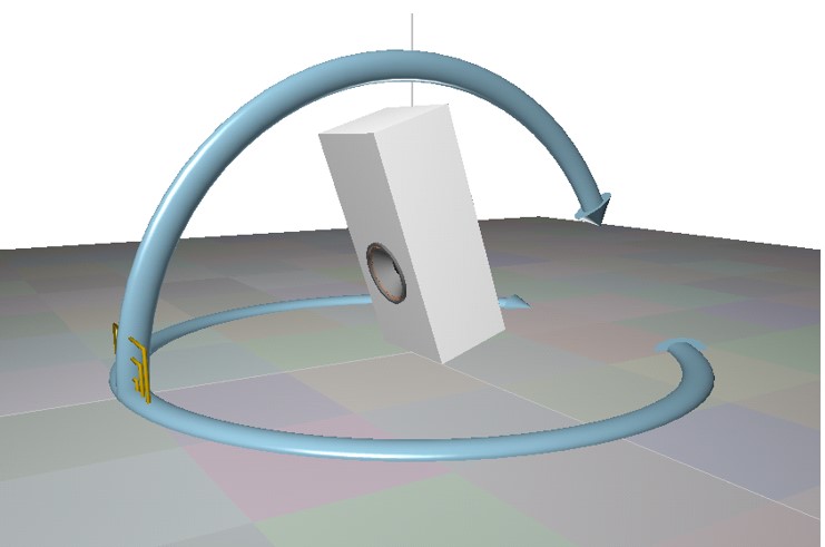
The 3D Layout in Figure 12 shows this domain in the ground plane configuration below. The boundary is drawn as a large flat plane. The simulation target is at the surface of the plane, and the enclosure is angled towards the target. This will then produce the on-axis response of the transducer.
Note that all radiation is above the plane. Therefore, the vertical polar plots would be expected to have no response for negative angles below the plane. The horizontal polar locations occur at the surface of the plane.
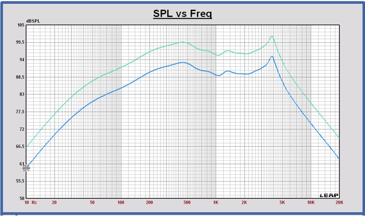
The graph in Figure 13 shows the response for both the Ground Plane simulation (green color) as well as the previous Full Space simulation (blue color). The curves have virtually identical shape, except for a difference of about 6dB. Indeed, the ground plane half space configuration approximates the anechoic response very closely but simply scaled +6dB higher. Since the enclosure was angled to allow the transducer to be on-axis with the target, the high frequency response would be expected to be similar as any on-axis response. Furthermore, since the target is located directly on the surface of the boundary, all radiation levels are doubled.
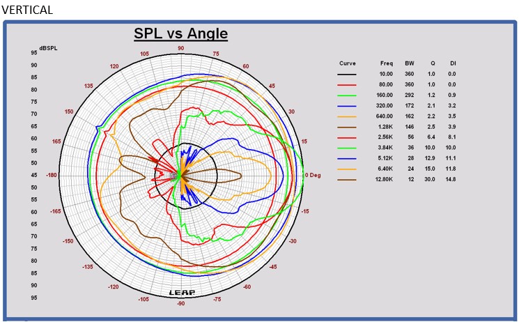
The horizontal and vertical polar graphs are shown in Figure 14 and Figure 15 for the Ground Plane configuration. There is now radiation 360° around the enclosure horizontally, but only 0-180 in the vertical direction as expected.
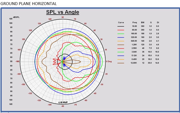
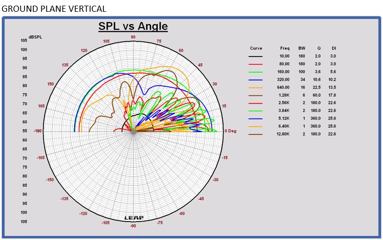
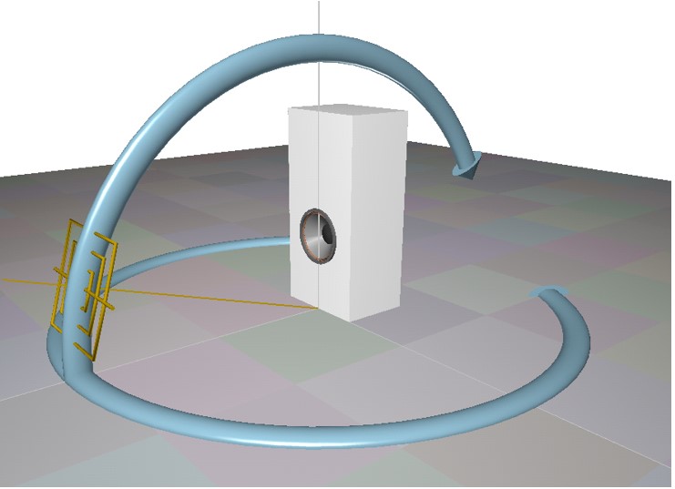
The 3D Layout in Figure 16 now shows this half space domain configured in the more general fashion with the target simulation point above the plane. The enclosure is not angled but simply placed flat on top of the plane. The target is located directly on-axis with the transducer. Whenever receiver positions do not lie on the surface of a boundary, there will always be reflections. For the configuration below, we would expect reflections to occur in the vertical polar response, but not in the horizontal.
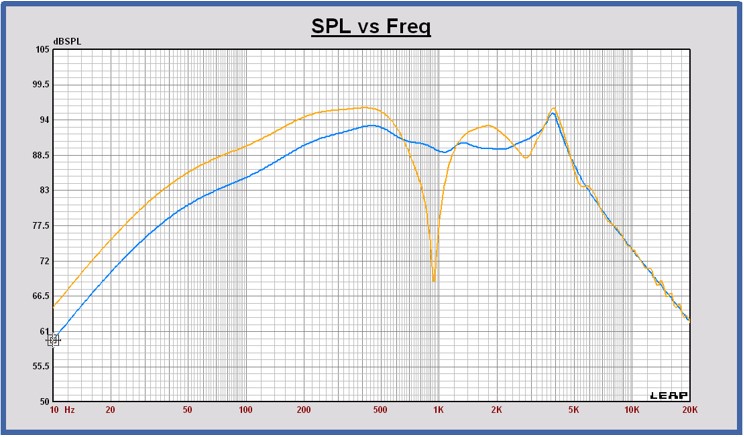
The graph in Figure 17 shows the response for both the general Half Space simulation (yellow color) as well as the previous Full Space simulation (blue color). The half space curve is 6dB higher than the full space curve at low frequencies, as one would expect from the 2π vs.4π field size difference. At mid frequencies there is a pronounced null in the half space response. This is the result of the boundary reflections. At frequencies above 4 kHz the response curves are nearly identical. This is where the transducer is highly directional, and does not direct any significant radiation towards the plane. As such, there are minimal reflections.
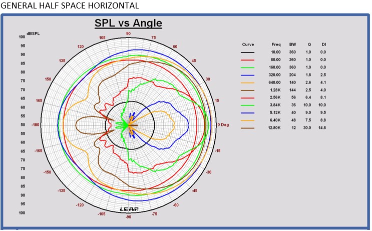
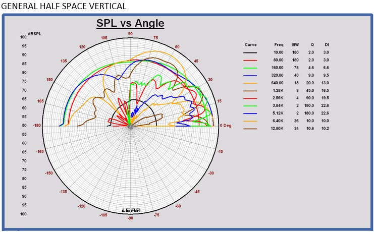
The horizontal and vertical polar graphs are shown in Figure 18 and Figure 19, for the general half space configuration. Again, there is radiation 360° around the enclosure horizontally, but only 0-180 in the vertical direction. Note that the on-axis position occurs at approximately 20° vertical.
References
- Leap EnclosureShop Reference Manual p. 139-150
