Crossover Filter Targets
In this technical page the LR4 filter targets will be described in detail. This filter is used in the Loudspeaker Design Example VCL EM2.
Other filter targets with different filter types like Butterworth, Elliptical, Duelund,… and with other filter slopes, can be created in the same way as described in this page. The filter polynomials and the filter blocks to be used in the CAD tool will be different.
Contents
LR4 Filter
The LR4 low pass filter transfer at a frequency fr consists of a cascade of two second order low pass filters at frequency fr with a Q factor equal to 0.707, two Butterworth second order low pass sections in series.
In the same way, the LR4 high pass filter transfer at a frequency fr consists of a cascade of two second order high pass filters at frequency fr with a Q factor equal to 0.707.
3-way LR4 crossover filter
For the loudspeaker design example VCL EM2, to realize a loudspeaker with the most flat SPL, power and directivity index the crossover frequencies are chosen at 250 Hz and at 2500 Hz.
With the chosen woofer Scanspeak 26W8534G00, that has a sensitivity of 89 dB on infinite baffle, the loudspeaker sensitivity can be designed at 83 dB and a F3 = 40 Hz in full space.
Create filter targets in the CAD tool
The VituixCAD main program can be used to create the crossover filter targets.
Start (VituixCAD)
Create a new project and save the project as a “vxp” file.
Drivers TAB
Select (VituixCAD -> Drivers)
Add 3 drivers, driver #1, driver #2 and driver #3 and set the default SPL of each driver to 83 dB.
Crossover TAB
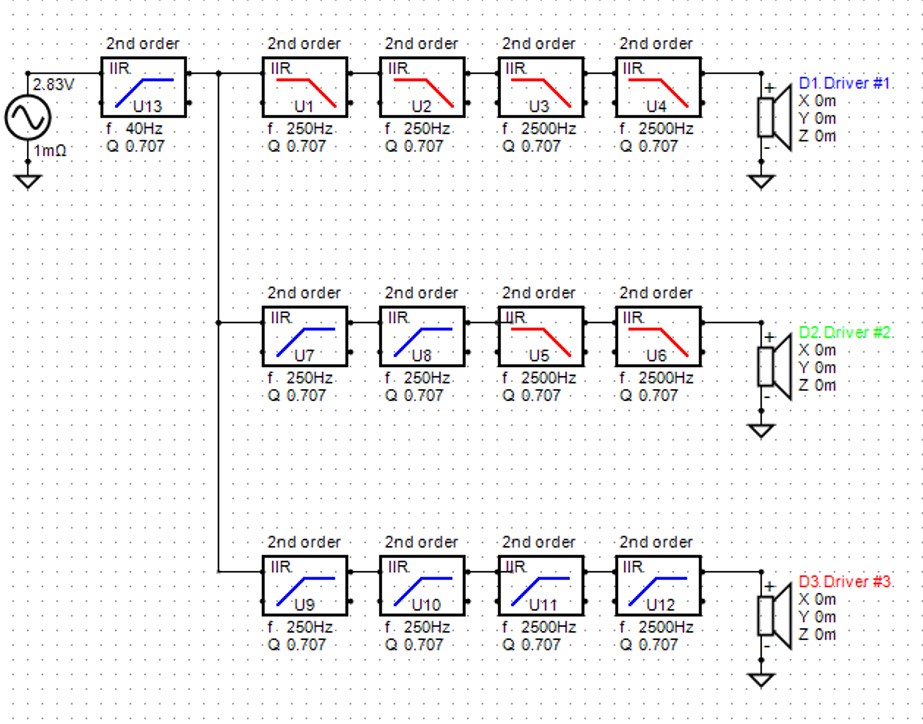
Make a schematic with filter blocks like mentioned in the figure below.

One “Active High Pass” filter block, 2nd order, f = 40 Hz, Q = 0.707 in series with the source for the F3 and low frequency target.
For driver #1, the woofer target: two “Active Low Pass” filter blocks, 2nd order, f = 250 Hz, Q = 0.707 and two “Active Low Pass” filter blocks, 2nd order, f = 2500 Hz, Q = 0.707, all in series.
For driver #2, the midrange target: two “Active High Pass” filter blocks, 2nd order, f = 250 Hz, Q = 0.707 and two “Active Low Pass” filter blocks, 2nd order, f = 2500 Hz, Q = 0.707, all in series.
For driver #3, the tweeter target: two “Active High Pass” filter blocks, 2nd order, f = 250 Hz, Q = 0.707 and two “Active High Pass” filter blocks, 2nd order, f = 2500 Hz, Q = 0.707, all in series.
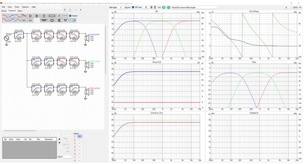
The following screen is now displayed in the main program.

In the SPL chart, the SPL target of each driver and the sum can be observed. The sum is flat at 83 dB and F3 is 40 Hz.
In the phase chart, all the driver target phases are aligned like expected for LR4.
In the filter chart, the target transfer function of each driver crossover filter is displayed.
Export filter targets to text files
Select woofer driver#1 by mouse click on driver#1.
Select (VituixCAD -> File -> Export-> Frequency response of driver )
Save the woofer target as a text file, for example “Target wf LR4 250 2500 83 dB.txt”.
Select also midrange and tweeter drivers and save the targets as text files, for example “Target mr LR4 250 2500 83 dB.txt” and “Target tw LR4 250 2500 83 dB.txt”. The 3 target curves will be used for the crossover filter design.
