
February 2021 – 3-way speaker with Purifi 4 inch midrange, Purifi passive radiator system, Bliesma Be tweeter and Duelund crossover
The VCL EX18 is a 3-way speaker concept using the new Purifi 4 inch as midrange.
The woofer is a passive radiator system with two 6.5 inch 4 Ohm woofers Purifi PTT6.5X04-NFA-01 in series and each woofer equipped with two Purifi PTT6.5PR-NF1-01 passive radiators.
The midrange is the Purifi 4 inch PTT4.0X04-NFC-01, placed in a closed box.
The tweeter is the Bliesma T25B-6 beryllium.
The crossover filter will be a 4th order Duelund filter.
Contents
- Specification Headlines
- Estimation Bill Of Material
- Speaker System
- Cabinet
- SPL and impedance curves of the transducers in the cabinet
- Off axis response, Power and Directivity Index of the transducers in the cabinet
- Duelund Crossover Filter
- Maximum excursion and maximum SPL with the LR4 filter
Specification Headlines
- System: 3-way, passive radiator system, analog X-over
- Woofer: 2 x Purifi PTT6.5X04-NFA-01
- Passive Radiator: 4 x Purifi PTT6.5NF1-01
- Midrange: Purifi PTT4.0X04-NFC-01
- Tweeter: Bliesma T25B-6
- Low frequency response: F3 = 37 Hz
- Sensitivity: 82 dB at 1m, 2.83 Vrms, full space
- SPL at maximum excursion, 37 – 20000 Hz: 104 dB, 1m, full space
- Crossover: Duelund 4th order at 220 Hz and 3000 Hz
- Impedance: mean value between 4 and 25 Ohm
- Cabinet dimensions: width x heigth x depth = 26 cm x 110 cm x 38 cm
Estimation Bill Of Material
- 4 x Woofer Purifi PTT6.5X04-NFA-01: 1480 euro
- 8 x Passive Radiator 4 x Purifi PTT6.5NF1-01: 1120 euro
- 2 x Midrange Purifi PTT4.0X04-NFC-01: 600 euro
- 2 x Tweeter Bliesma TB25B-6: 500 euro
- Components high quality crossover: 800 euro
- Components medium quality crossover: 500 euro
- Cabinet material: 100 euro
- Cabinet Accessoires: 100 euro
- Total with high quality crossover 4700 euro
- Total with medium quality crossover 4400 euro
Speaker System
Transducers
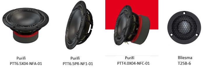
Purifi PTT6.5X04-NFA-01, Purifi PTT6.5PR-NF1-01, Purifi PTT4.0X04-NFC-01, Bliesma TB25B-6
The Purifi PTT6.5X04-NFA-01 is a 6.5 inch woofer. The maximum linear excursion is +/- 10 mm. The harmonic distortion is very low, better than -40 dB at low frequencies and better than -60 dB at 1 kHz. The transducer has been measured by HifiCompass. To match with the midrange sensitivity two of these woofers are placed in series. They are mounted at both side panels of the cabinet to realize force cancelling.
The Purifi PTT6.5PR-NF1-01 is a 6.5 inch passive radiator. The maximum linear excursion is +/- 15 mm. Four of these transducers together with the 2 woofers are placed in a 25 L cabinet to realize a very powerful passive radiator woofer system. The SPL at maximum excursion will become 104 dB at 1m, 2.83Vrms. This is very good for such compact system.
The Purifi PTT4.0X04-NFC-01 4 inch midrange is a recent development. The harmonic distortion is very low, better than – 55 dB in the frequency operating range 200 – 4000 Hz. This transducer has been measured by HifiCompass.
The Bliesma T25B-6 is a 1 inch Beryllium tweeter. The harmonic distortion of this transducer is very low, better than -55 dB between 2500 and 8000 Hz and better than -45 dB to 20 kHz. This transducer has been measured by HifiCompass. The dome of this transducer is flush mounted with its face plate which results in an excellent off axis behaviour.
Transducer constant piston behaviour
To visualize the transducer constant piston behaviour, the on-axis SPL on infinite baffle is calculated using the TS parameters and compared with the measured on axis SPL.
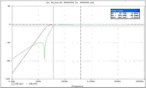
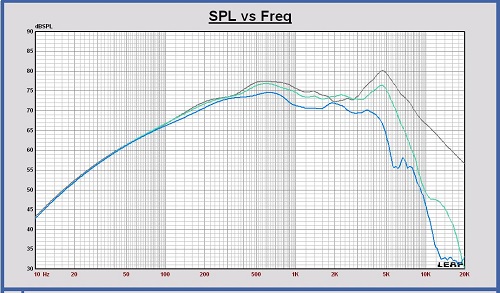
Woofer Purifi PTT6.5X04-NFA-01, calculated SPL on-axis(grey) vs. measured SPL on-axis (green)
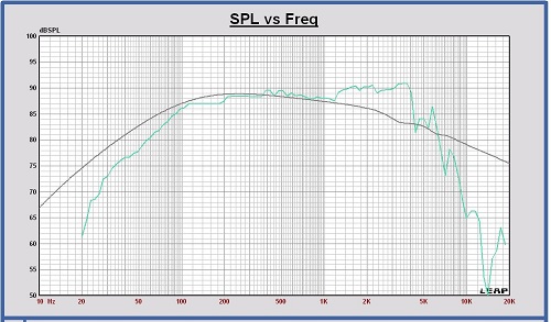
The curve shapes are the same up to 1200 Hz. It means that this woofer has a constant piston behaviour up to 1200 Hz. For higher frequencies the measured SPL is higher than the calculated SPL, non-constant piston behaviour is starting. This is a normal behaviour of many woofers.
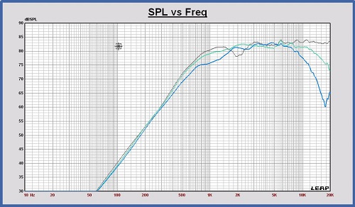
Midrange Purifi Purifi PTT4.0X04-NFC-01, calculated SPL on-axis(grey) vs. measured SPL on-axis (green)
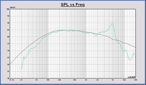
The curve shapes are the same up to 2000 Hz. It means that this midrange has a constant piston behaviour up to 2000 Hz. The transducer will be used between 220 and 3000 Hz.
Passive Radiator System – Small Signal Analysis
Two 6.5 inch Purifi woofers and four 6.5 inch Purifi passive radiators are used in this 3 way speaker.
As a reference to calculate the responses of the passive radiator system, the article “Passive-Radiator Loudspeaker Systems” by Richard H.Small is used. In this post only the parameter values and the calculation results are summarized. For a more detailed understanding, the reference article can be used.
For two Purifi woofers in series: fs = 30 Hz; Vas = 0.052 L; Qts = 0.27
For four passive radiators: Vap = 104.8 L
For a cabinet volume = 25 L, fp = 17 Hz (total cone mass for each passive radiators adjusted to 80 g), no cabinet filling and a serial source resistance of 0.5 Ohm
Then: Ts = 5.3 ms; Tp = 9.4 ms; alfa = 2.08; delta = 4.19; QT = 0.31
With the above parameter values, the frequency response on infinite baffle can be calculated, using the formula as mentioned in the reference article.
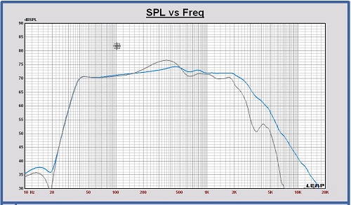
The green curve shows the passive radiator response, the red curve a Butterwoth B4 response at the same system frequency to compare with. F3 = 37 Hz with these parameter values.
Remark that these responses are a result with low losses, but these calculated responses are already indicative.
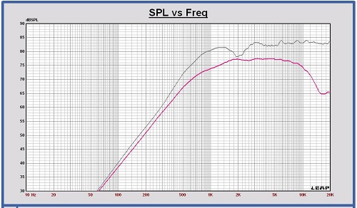
Simulating the frequency response on infinite baffle in Leap with the same parameters, is shown in the next graph. The results are comparable. Cabinet filling is applied in the Leap simulation.
As a first conclusion of this passive radiator system study, the cabinet volume can be chosen 25 L and the total mass of each passive radiator cone 80 gram. These values can be fine tuned with measurements.
Midrange – Small Signal Analysis
The 4 inch Purifi midrange is placed in a closed box of 15 L filled with sheep wool.
For this midrange: fs = 38 Hz; Vas = 6.4 L; Qts = 0.30 on infinite baffle.
Placed in the 15 L cabinet: fc = 41 Hz and Qtc = 0.35.
Cabinet
Cabinet dimensions
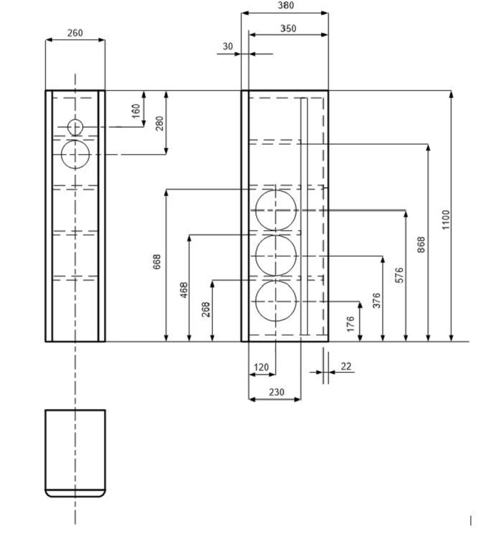
At the backside inside the enclosure there is some place for the crossover filter.
Front, top, bottom and internal back panel are 30 mm. Bracing is 18 mm and backside covering panel is 22 mm.
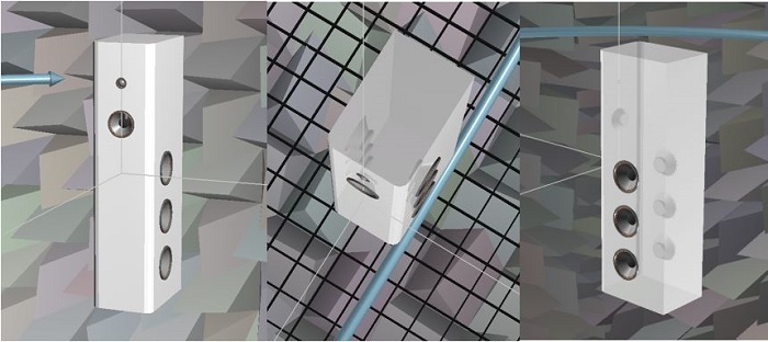
3-D look in Leap
SPL and impedance curves of the transducers in the cabinet
These are the SPL and impedance curves of the transducers placed in the cabinet in free space at 1 meter, 2.83 Vrms . Also the SPL responses on infinite baffle are shown to see the impact of the cabinet shape on the response.
These simulated curves are used for a first crossover filter design.
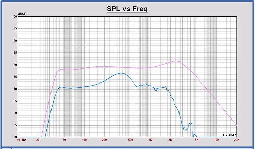
SPL 2 woofers and 4 passive radiators in the cabinet on-axis in free space (blue curve) and on infinite baffle (pink curve)
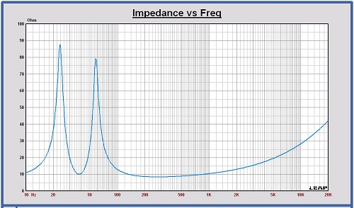
Impedance 2 woofers and 4 passive radiators in the cabinet
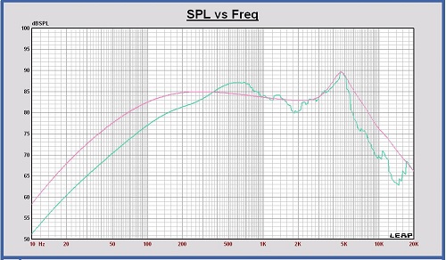
SPL midrange in the cabinet in free space (green curve) and on infinite baffle (pink curve)
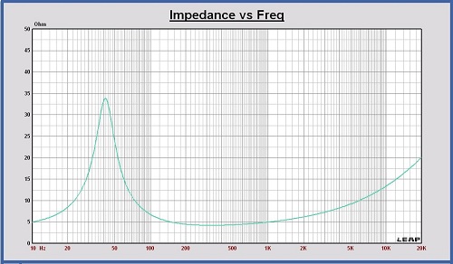
Impedance midrange in the cabinet
SPL tweeter in the cabinet in free space (red curve) and on infinite baffle (pink curve)
Horizontal polar diagram midrange in cabinet free space at 320 – 640 – 1200 – 2500 – 3800 Hz
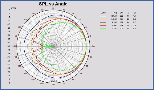
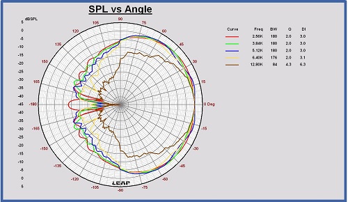
Horizontal polar diagram tweeter in cabinet free space at 2.5 – 3.8 – 5.1 – 6.4 – 12.8 kHz
Off axis response, Power and Directivity Index of the transducers in the cabinet
To choose the optimum crossover frequency for this speaker, the horizontal and vertical SPL off axis responses of woofer, midrange and tweeter have been simulated in steps of 15 degrees, the speaker placed in free space at 3m distance. The power is calculated out of the mean value of the curves. In this case, the power is represented as the SPL of an omnidirectional source at 3m distance in free space with a SPL value equal to the power.
Horizontal SPL on and off axis of the woofer in the cabinet at 0, 30 and 60 degrees
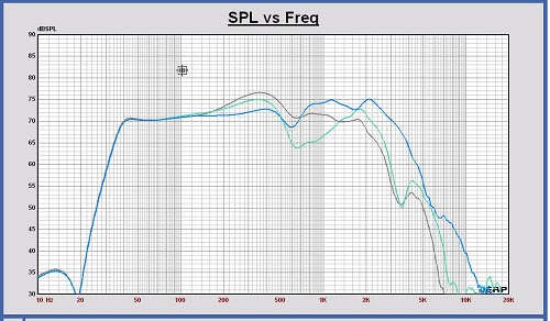
Horizontal SPL on and off axis of the midrange in the cabinet at 0, 30 and 60 degrees
Horizontal SPL on and off axis of the tweeter in the cabinet at 0, 30 and 60 degrees
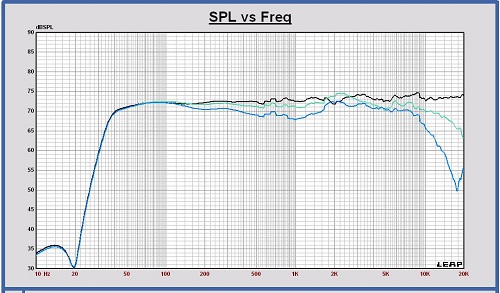
SPL on axis and Power of the woofer in the cabinet in free space
SPL on axis and Power of the midrange in the cabinet in free space

SPL on axis and Power of the tweeter in the cabinet in free space
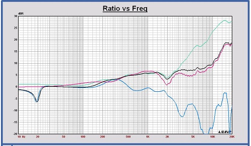
Directivity Index DI in free space of the woofer, midrange and tweeter in the cabinet
The Directivity Index plot shows that, to keep the DI of the sum response flat, the crossover frequencies can be located at 220 and 3000 Hz.
The SPL on-axis dip of the tweeter and also the midrange, and the corresponding DI dip around 2 kHz, are related to the speaker width.
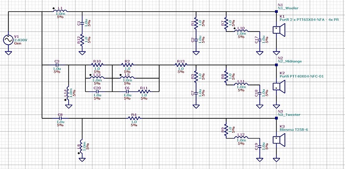
Duelund Crossover Filter
A Duelund filter type is chosen for the crossover filter of this speaker.
A Duelund filter is a crossover approach that the filter functions of the different speaker ways remain in phase at all frequencies. The sum response has an all pass filter behaviour.
Some parameters can be chosen to define the Duelund filter type. Parameter ‘a’ determines the damping of the second order filter sections. The order can be chosen to define the slope of the curves in the stop band of the different ways.
For this speaker, the 4th order Duelund filter is chosen and a = 4. It means that the Q factor of the second order filter sections is 0.25. There is no overshoot or ringing in the impulse repons and the group delay response of the sum shows no peaking.
With the Duelund 4th order filter, the slope of the low pass and high pass sections in the stop band is 4th order. With the high applied damping of the sections, the slope is 2nd order in the first part of the stop band. For the bandpass section, the slope of the curves is 2nd order in the two stopbands.
The Duelund 4th order filter, a = 4 has the same response and behaviour as two cascaded LR2 sections at two natural frequencies equal to the crossover frequencies.
There are also 8th order Duelund filters with higher stop band slopes for the low and high sections. Later on this filter will be considered also.
A complete description of the Duelund filter is described in the Tech Corner.
Targets Crossover Filter Duelund 4th order, a = 4 at 220 and 3000 Hz
Crossover filter schematic configuration
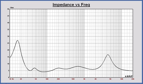
Impedance with crossover flter
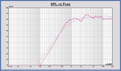
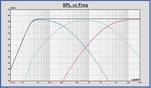
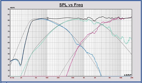
SPL on axis of the filtered drivers and the sum at 1m, 2.83 Vrms
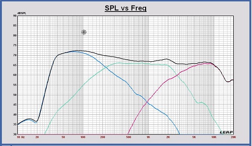
SPL off axis of the filtered drivers and the sum at 3m, 2.83 Vrms
Power response of the filtered drivers and the sum in free space at 3m, 2.83 Vrms
The mutual distance between the drivers in vertical direction is not included in this calculation. With this distance included, an extra power dip at the crossover frequencies will appear with a DI peak as a consequence.
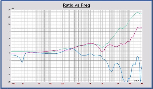
Directivity Index in free space of the filtered drivers and the sum
Impulse Reponse of the filtered transducers sum
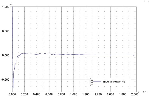
As expected out of the definition of the 4th order, a=4 Duelund filter, there is no overshoot or ringing in the impulse response.
Maximum excursion and maximum SPL with the Duelund filter
Maximum Excursion
With the designed Duelund 4th order filter, each passive radiator has its maximum excursion of 15 mm peak at 34 Hz for a voltage of 36.3 Vrms at the input of the filter.
The excursion of woofer, midrange and tweeter have been calculated also at 36.3 Vrms.
Excursion at 36.3 Vrms of woofer(blue), passive radiator (yellow), midrange(green) and tweeter(red)
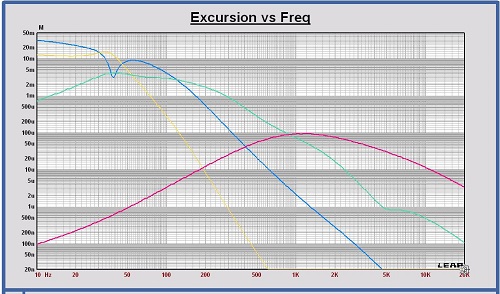
For each woofer, the excursion is maximum at 54.5 Hz and equal to 9.08 mm peak. The maximum specified linear excursion of the Purifi PTT6.5X04-NFA-01 is 10 mm peak.
For each passive radiator, the excursion is maximum at 33.8 Hz and equal to 15.0 mm peak. The maximum specified linear excursion of the Purifi PTT6.5PR-NF1-01 is 15 mm peak.
The midrange excursion is maximum at 49.9 Hz and equal to 4.13 mm peak. The maximum specified linear excursion of the Purifi PTT4.0X04-NFC-01 is 8.8 mm peak.
The tweeter excursion is maximum at 1064 Hz and equal to 0.095 mm peak. The maximum specified linear excursion of the Bliesma T25B-6 is 1.0 mm peak.
Maximum SPL
The maximum SPL for the operating frequency range 34 – 20000 Hz at maximum excursion of each passive radiator is 104 dB at 1m, 36.3 Vrms at the input of the crossover filter.
