Passive filter
The design of a passive crossover filter using VituixCAD is described in this page.
Contents
- Preparing the crossover design and creating the filter target curves
- Acoustic centers setting
- Passive filter schematic design
- Some guidelines to design a passive filter crossover filter
Preparing the crossover design and creating the filter target curves
Preparing the crossover can be done like described in Tech Page 19 – VCLLabs and creating the targets like described in Tech Page 11 – VCLLabs.
Acoustic centers setting
For a passive filter design the acoustical center offsets of the drivers have to be added.
For the loudspeaker example VCL EM2, the woofer acoustic center is 40 mm behind the tweeter acoustic center and the midrange is 20 mm behind.
Select each driver with the mouse and adapt the z coordinates.
Z coordinate driver #1 = 40 mm
Z coordinate driver #2 = 20 mm
Z coordinate driver #3 = 0 mm
Passive filter schematic design
A passive filter network are added between the source and the three drivers.
Different passive filter compoents can be chosen in the VituixCAD Crossover menu.

Selecting a component in the schematics, allows to set the componet parameters like value, DCR for coils and ESR for capacitors.
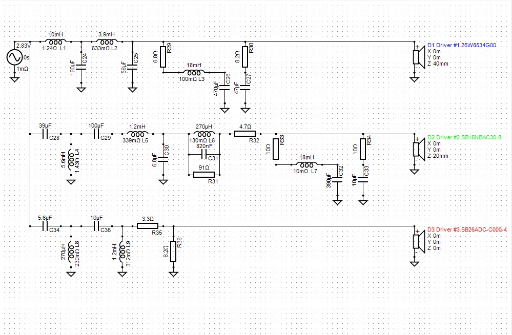
Below a passive filter schematic is displayed like being designed for the Loudspeaker Example VCL EM2, a Linkwitz Riley LR4 filter at 250 and 2500 Hz.

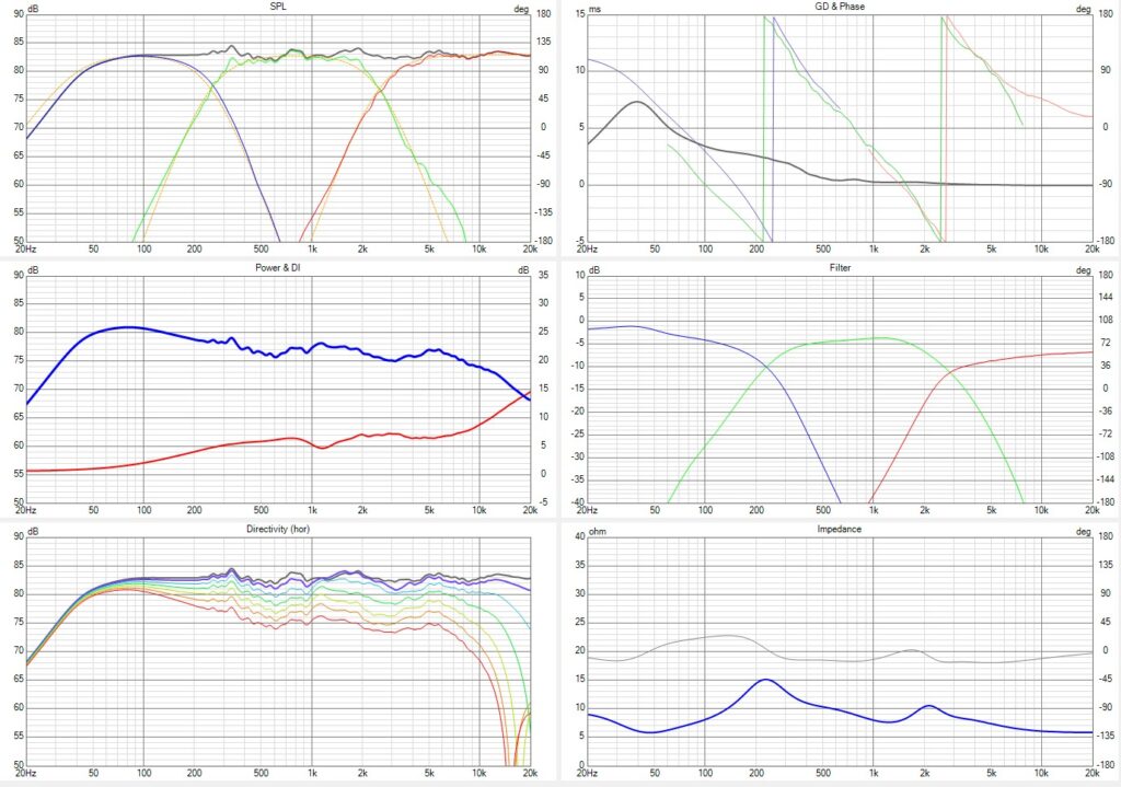
While making the passive filter design, the charts of all the reponses are displayed in real time. That is a very interesting feature in VituixCAD to optimize the passive filter for the responses to fit on their targets.

Some guidelines to design a passive filter crossover filter
- At first some components to compensate for the high frequency increase of the impedance and the impedanca peak a the resonance frequencies of the woofer and midrange systems, must be chosen. In most cases there is no need to add such compensation for the tweeter.
A series resistor – capacitor and a series resistor – capacitor – coil network are placed parallel with the woofer and the midrange. - Then the passive networks between each driver and the source are added.
It is interesting to see the filter targets now. The passive network can be designed for the filtered driver responses to become equal to their targets. - the phase responses of the drivers should become on target around the crossover frequencies with a frequency overlap as wide as can be realized. If needed, to compensate for the acoustic center offsets, an all pass filter can be added in the tweeter filter to create some delay.
- the total impedance at the input of the filter shouldn’t become not too low. If possible to keep the input impedance higher than 4 Ohm at each frequency.
- the power response and the DI curves should be as flat as possible. Sometimes a little deviation from target for the SPL or/and phase curves can help to optimize the power and the DI in the best way.
- there is no real rule how to define the passive network. One can start with some standard networks for the chose filter type, in this case LR4, but it is the combination of both the passive filter and the acoustical SPL of the driver which have to result in the wanted response of a driver conform the filter target. While adding the components, the filtered drivers have to be monitored in the SPL and phase chart, to fit in the best way on the LR4 target curves. One gets more and more experienced by making more designs and study existing crossover designs.
