Motional feedback of a woofer transducer
Contents
- Introduction
- Block diagram
- Functional blocks
- Block diagram with functional blocks
- Open and closed loop responses
- Design example
- Design of the MFB loop
- Audio input filter
- Loop gain measurement
Introduction
Motional FeedBack (abbreviated MFB) of a woofer transducer is a loudspeaker system where the acceleration is controlled by a feedback loop. At low frequencies, up to a few hundred Hz, the cone is moving as a constant piston without cone breakup. In that frequency range the sound pressure level of the transducer on infinite baffle is proportional to the acceleration of the cone.
Measuring the acceleration with an accelerometer mounted on the voice coil, comparing its output voltage with the incoming audio signal and send the difference via a controller back to the loudspeaker terminals, the acceleration of the transducer can be steered in a controlled way.
Using such motional feedback loop improves the distortion and creates the opportunity to extend the low frequency response.
Block diagram
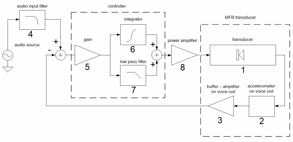
The accelerometer 2 is mounted on the voice coil of the transducer 1. The accelerometer output is buffered and amplified with a stage 3 that is also mounted on the voice coil.
The audio signal is filtered 4 and will be the reference for the transducer SPL output.
The buffer output voltage and the filtered audio input signal are compared and the difference is sent to the input of the power amplifier 8 via the controller.
To make the closed loop stable and to set the open loop gain and the bandwidth of the loop to the wanted values, the controller is added to the loop.
The controller consists of a gain block 5, an integrator 6 and a low pass filter 7. The parameters of these controller blocks are adjusted for this control loop.
Functional Blocks
Transducer – block 1
The transducer is mounted in a closed box.
The Thiele-Small parameters of the transducer in the closed box are:

The transfer a/u, the acceleration over the voltage on the terminals as a function of frequency is:

This is a second order high pass filter behavior at the frequency fc with a Q-factor Qtc and a gain equal to BL/(Mms*Re) at high frequencies.
At high frequencies the acceleration, above 1 kHz for most of the transducers, decreases due to the inductance Le of the voice coil. It can be assumed as a first order low pass filter behavior starting at the frequency Re/(2 * pi *Le).
The total transfer of the transducer block 1 becomes:

See also the article “Transducer electro-mechanical model” at https://vcllabs.com/tech-page-03/
Accelerometer – block 2
The sensitivity Mo of the accelerometer is expressed in mV/g, where g = 9.81 m/s2 , the gravitation acceleration constant. To express the transfer in mV/(m/sec2) the value of Mo has to be divided by 9.81.
Also the dynamic range of the accelerometer is specified.
As an example, for the TE-connectivity ACH-01 accelerometer: Mo = 11 mV/g or 1.1 mv/(m/s2) and the dynamic range is equal to 150 g or (150 x 9.81) m/s2.
Accelerometer Buffer – Amplifier – block 3
A buffer-amplifer is placed behind the accelerometer to set the output level of the accelerometer to the desired value and make the output low impedant.
The amplifier gain has to be chosen in order to set the audio input level at the wanted level for the acceleration of the transducer to be maximum.
Audio input filter – block 4
The MFB loop will be designed in a way the SPL output of the transducer on infinite baffle will follow the audio input signal in the operating frequency area. If a low pass filter is applied on the audio input signal, the SPL of the transducer on infinite baffle will follow the filtered audio signal.
As an example, a bandpass filter will be chosen consisting of a second order high pass filter at frequency f1, Q-factor Q1 and a second order low pass filter at frequency f2, Q-factor Q2.
The transfer of the audio input filter block 4 becomes:

Controller – blocks 5 – 6 – 7
The controller has to be designed to make the closed loop stable, to fix the unity gain bandwidth at low and high frequencies and to set the loop gain value in the operating frequency area.
Controller functional blocks:
- the gain block 5 is added to fix the loop gain in the operating frequency area.
- the integrator block 6 is added to make the closed loop stable at low frequencies.
- the low pass filter block 7 is added to fix the unity gain bandwidth at high frequencies.
Transfer of the controller functional blocks:
- the transfer of the gain block 5 = K1.
- the transfer of the integrator = 1/(s/f3); the gain = 1 at frequency f3 , first order increasing below f3 and first order decreasing above f3.
To avoid drifting the DC gain of the integrator is set to a fixed value. The integrator is implemented as a first order low pass filter at frequency f3/10 with a gain = 10.
The transfer of integrator block 6 is:
- the transfer of low pass filter block 7 at frequency f4 is:

Power amplifier – block 8
The amplifier gain is about 20 times for most power amplifiers.
The transfer of power amplifier block 8 = K2.
Block diagram with functional blocks
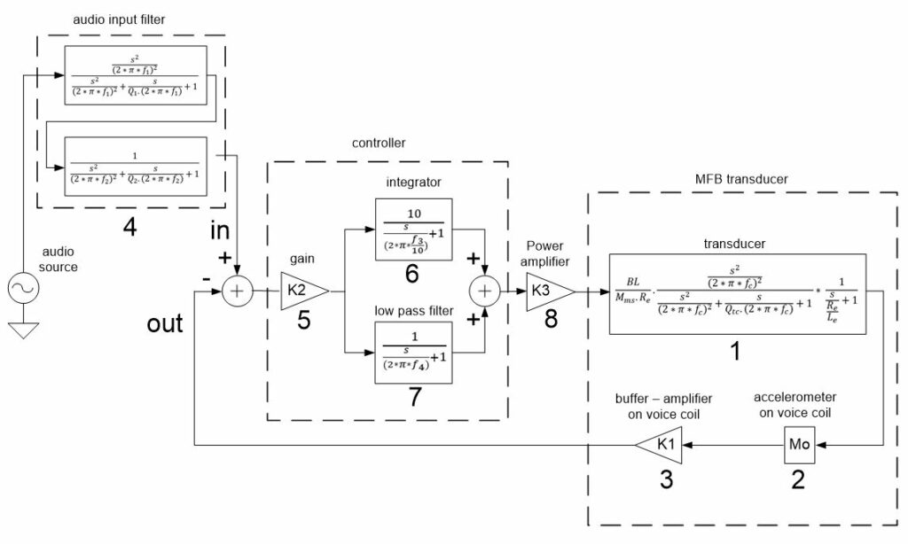
MFB loop parameters:
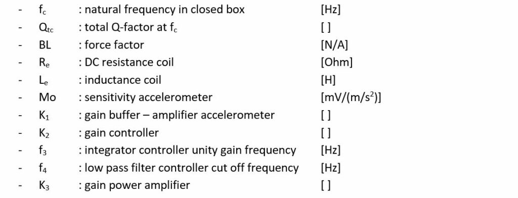
Audio input filter parameters:

Open and closed loop response
This is a simplified representation of a control loop with loop gain H(s):

The closed loop response:

The error response:

In the operating frequency area where H is large, v(out)/v(in) becomes equal to 1, v(out) will follow v(in).
The stability of the closed loop response has to be investigated. Closing the loop can lead to peaks in the closed loop response H/(H + 1) caused by poor phase margin at the loop unity gain frequencies. The controller of the loop is configured to guarantee a stable behavior of the closed loop response.
Design example
Transducer in closed box
The Eton woofer 11-212 is chosen. The transducer is placed in a closed box of 20 L.
The parameters of this closed box system are:

It is recommended to choose the volume of the cabinet in a way that fc becomes 50 – 60 Hz and Qtc = 0.6 – 0.8.
In that way the open loop gain at 100 Hz can become high.
Accelerometer on voice coil
The TE-connectivity ACH-01 accelerometer is chosen.

Power amplifier
The gain of the power amplifier is chosen 20.
Design of the MFB loop
Target specification of the MFB loop (example)
- The unity gain frequencies of the open loop are chosen 10 Hz and 1000 Hz.
Around 100 Hz, the middle of the operating frequency area, the loop gain has to be around 10.
The loop bandwidth will be limited to 1000 Hz, for several reasons. The inductance of the voice coil causes a quasi first order low pass filter around 1 kHz. Above about 2 kHz, the acceleration of the cone, the transfer of the accelerometer and the mechanical coupling of the accelerometer to the voice coil become more and more affected by mechanical break-ups, causing non-linear, unpredictable behavior and phase lag. - The woofer SPL is maximum at an audio input level = 1 Vrms.
- The audio input filter has to be configured for a woofer SPL frequency response being a bandpass filter. A second order Butterworth high pass filter at 30 Hz and a second order Linkwitz-Riley low pass filter at 400 Hz is chosen.
For this example the filter will be configured for an infinite baffle application.
Maximum acceleration (SPL) of the woofer in the closed box
The excursion of the cone has to be limited to the maximum linear excursion at the low frequency limit of the application and below it. For the example, this frequency is 30 Hz. The maximum excursion of the Eton 11-212 is 5 mm peak.
Excursion @ Eton 11-212 in closed box 20L at 1 Vrms
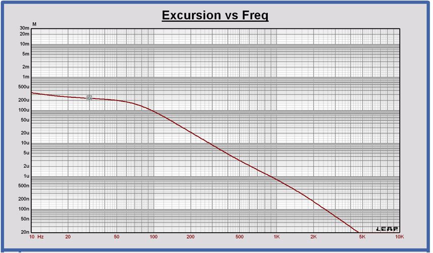
At 30 Hz the excursion is 233 µmrms or 329 µm peak at 1 Vrms input. The excursion becomes at its maximum of 5.5 mm peak at 16.7 Vrms input.
At 30 Hz and 16.7 Vrms, the acceleration is equal to 136 m/s2 rms.
In the application the acceleration at 100 Hz is 3 dB higher.
The maximum acceleration at 100 Hz is equal to 192 m/s2 rms.
The values of the excursion and the acceleration can be calculated using the equations of the article “Transducer electro-mechanical model” at https://vcllabs.com/tech-page-03/ or can be simulated using a software tool.
For the excursion x:

For the acceleration a:

Gain of the accelerometer buffer – amplifier
Knowing the maximum acceleration amax of the woofer and using the transfer Mo of the accelerometer, the gain value of the accelerometer buffer – amplifier can be calculated, in a way that the acceleration of the woofer is maximum 192 m/sec2 at 1 Vrms audio input level.
The value of the gain K1 in the functional block diagram can be calculated.
V(out) = amax * Mo * K1 or K1 = V(out)/(amax * Mo)
For the example K1 = 1V/(192 m/s2 * 0.0011 mV/(m/s2) = 4.7
MFB open and closed loop frequency responses
Variables that are already defined in the functional block diagram:

The open loop gain exclusive the controller looks as follows:
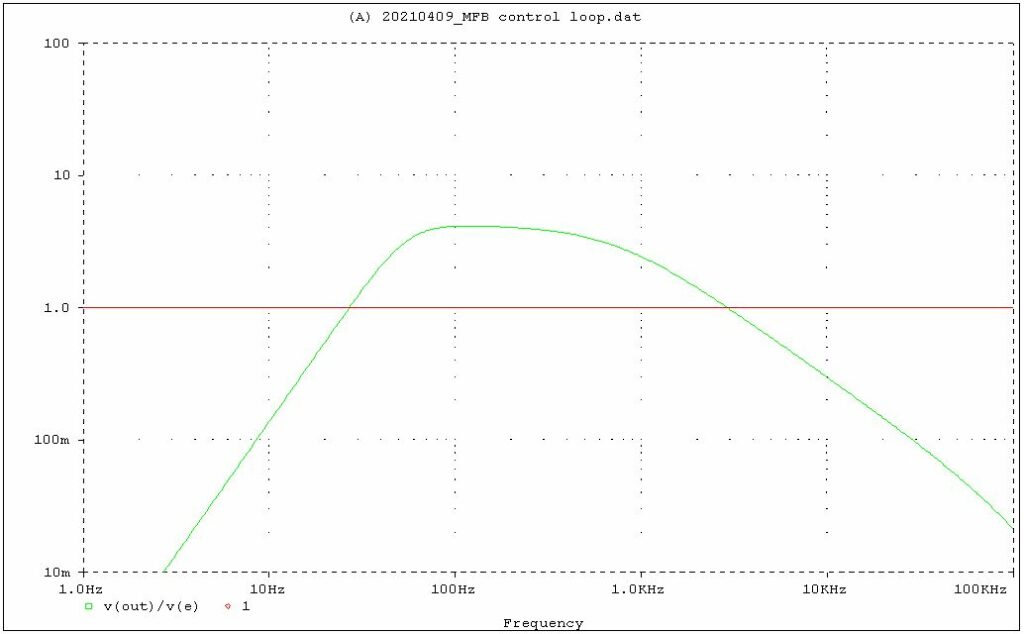
The gain at 100 Hz is 4.1. The specification target is a gain of 10 at 100 Hz. To realize this the controller gain K2 is set to 2.5.
For K2 = 2.5, the open loop is:
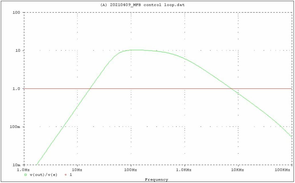
The loop gain at 100 Hz is 10.2 now.
Looking to the closed loop response v(out)/v(in) with this last open loop gain is shown in the following graph.
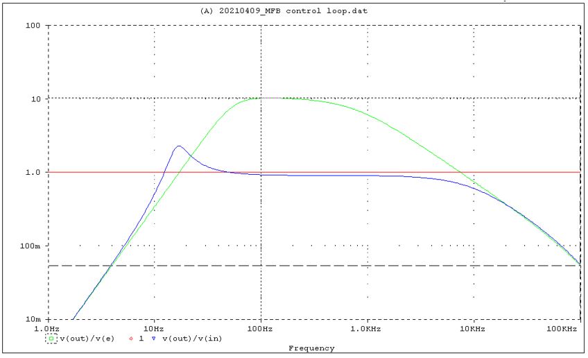
The closed loop (blue curve) is peaking at low frequencies, because the open loop gain phase is close to 180 degrees at that frequency. The phase margin is too low, only 25 degrees. The closed loop looks stable at high frequencies for the used transducer – accelerometer model in this example. Mechanical break ups of transducer cone and accelerometer above 1 kHz are not included yet in the model. If measurements of the transducer-accelerometer frequency response are available, it is recommended to use these for the closed loop simulation.
The open loop unity gain frequencies are 16 Hz and 7.3 kHz. They are wanted to be around 10 Hz and 1 kHz.
To realize more phase margin and damp the closed loop peak at low frequencies, a first order integrator is added to the controller at 20 Hz. Parameter f3 of the controller becomes equal to 20 Hz.
To make the loop unity gain frequency lower to 1000 Hz, a first order low pass filter is added to the controller at 80 Hz.
The parameters of the controller are:

The open and closed loop gain become:
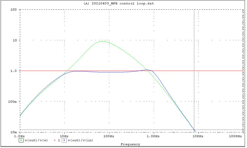
The closed loop response v(out)/v(in) is equal to about 1 in the frequency area 10 Hz to 1 kHz with less peaking.
The open loop unity gain frequencies are 11 Hz and 720 Hz.
The open loop gain at 100 Hz is equal to 9.1 .
Audio input filter
To realize the SPL output being a bandpass function between 30 Hz and 400 Hz, the input filter parameters are set as follows:

With the MFB active, Vin and Vout will look like:
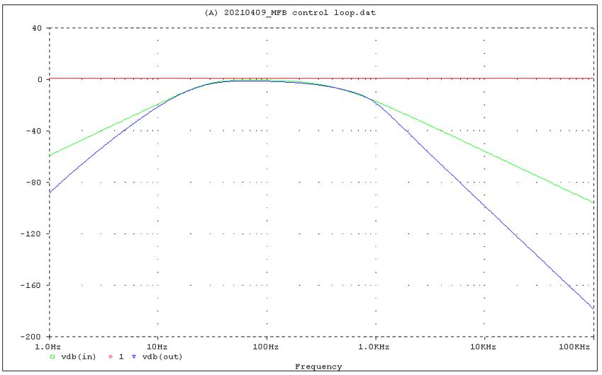
Vin in green color and Vout in blue color.
As can be expected the SPL output is following the filtered audio input within the MFB operating range 10 Hz to 1 kHz.
The input filter parameters can be further optimized in a way the SPL output will follow even better standard filter targets like Butterworth, Linkwitz-Riley or other, more far outband.
Acceleration, excursion and SPL at maximum excursion for an infinite baffle application
Acceleration, excursion and SPL at maximum excursion @ Vin = 1 Vrms ; MFB loop active
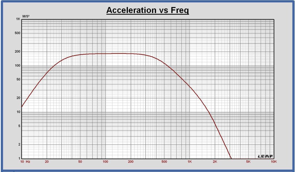
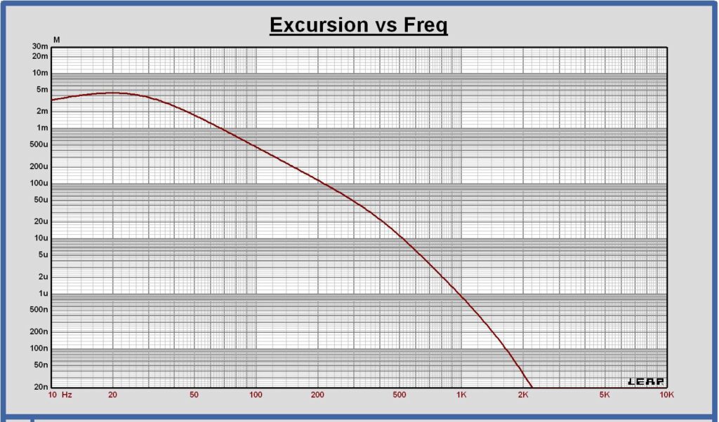
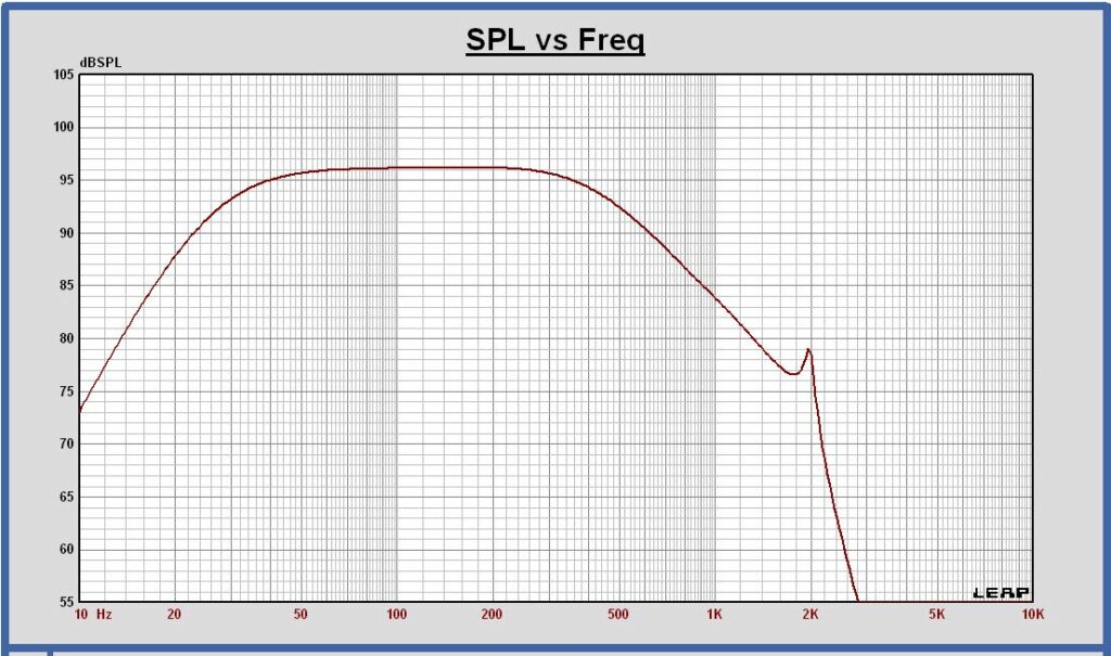
Remark:
For this example the audio input filter is calculated for an infinte baffle application.
With the cabinet placed in a full space environment the input filter has to be configured in a different way to compensate for the baffle step behavior. This is not considered in the filter calculation of this article.
Loop gain measurement
Block diagram of a control loop
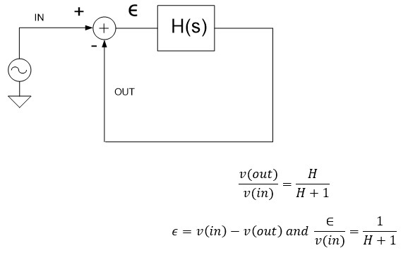
Measurement of open and closed loop responses
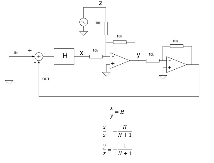
The loop gain can be measured in an easy way by adding a two stage opamp circuit in the loop.
The circuit has a gain = +1 and has to be placed behind a low impedance output and in front of a high impedance input, in a way the behavior of the loop will not be affected.
For the MFB loop it can be placed in front of the power amplifier input for example.
The input is kept zero and an error z is injected in the loop. The open and closed loop parameters transfers y/x, x/z and y/z can be measured.
