
DSP active filter using biquads
An example of a DSP filter design for miniDSP 96k in VituixCAD is described.
At the moment the crossover design with generic fuctional blocks has been designed, the project can be used to make the miniDSP96k filter using biquads.
Contents
Crossover design with generic filter blocks
Start (VituixCAD).
Open the “vxp” project of the crossover with generic functional blocks.
Important, select (VituixCAD -> Options-> set the “Save chart overlay to project” to on.
Important, to make an miniDSP96kcrossover design, select (VituixCAD -> Options-> Frequency Responses) and set the DSP system to “miniDSP 96k”
Important remark:
MiniDSP parametric equalizers have different frequency responses compared with some other brands or CAD tools for the same settings of the Q-factor. In miniDSP the Q-factor of the equalizer is defined in a different way.
Compared with the VituixCAD Parametric Equalizer it is different also, if the DSP system is set to “Analog”.
As a consequence a crossover design with generic filter blocks (and the DSP system set to “Analog”!) has to be adapted. The Parametric equalizer Q settings in the schematic must be modified.
In general, if only a digital crossover design will be made, it is better to set the DSP system not to “Analog” and set the DSP system directly to the used DSP, in this case “miniDSP96k”
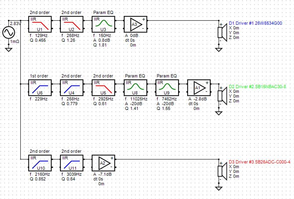
See below the schematic of the crossover filter with generic filter blocks for miniDSP96k.
Biquad text files for miniDSP 96k
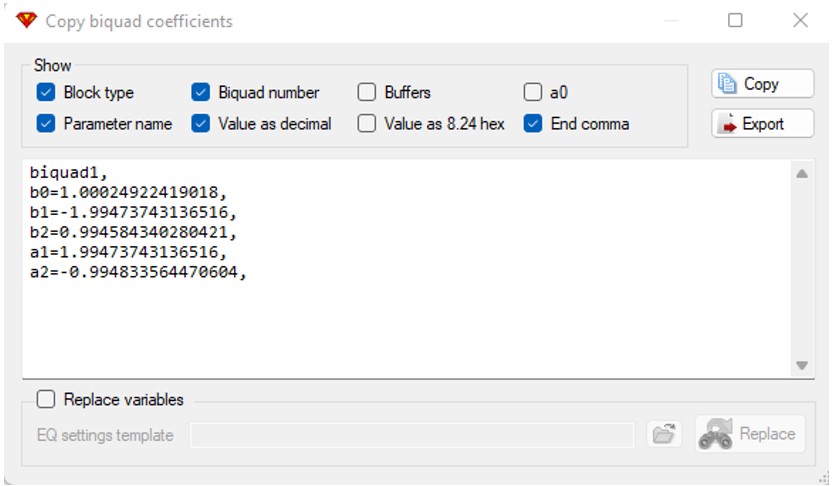
For each filter block, a copy of the biquad coeffs can be realized and exported to a txt file.
Select a filter block with the cursor and with a right mouse click, select “Copy Biquad coeffs”.
In the pop-up window the biquad coeffs can be exported to a text file.
Woofer
biquad1,
b0=0.000017657261017,
b1=0.000035314522034,
b2=0.000017657261017,
a1=1.98154405887678,
a2=-0.981614687920849,
biquad2,
b0=0.00007638418242,
b1=0.00015276836484,
b2=0.00007638418242,
a1=1.98587031713234,
a2=-0.986175853862022,
biquad3,
b0=1.00024922419018,
b1=-1.99473743136516,
b2=0.994584340280421,
a1=1.99473743136516,
a2=-0.994833564470604,
Delay settings in DSP
To compensate for the acoustical center differences between the three drivers, delay settings have to be defined in DSP.
In the miniDSP SW plug-in, delay in [ms] and distance in [m] can be defined.
distance s = sound speed v * time t
For example, to compensate for a tweeter, which position is 2 cm forwards, the time t is equal to 0.06 ms.
