May 2026 – 3-way full range dipole speaker – Audio Technology woofers and midrange – Mundorf AMT – Digital and analog passive crossover filter

Project scope
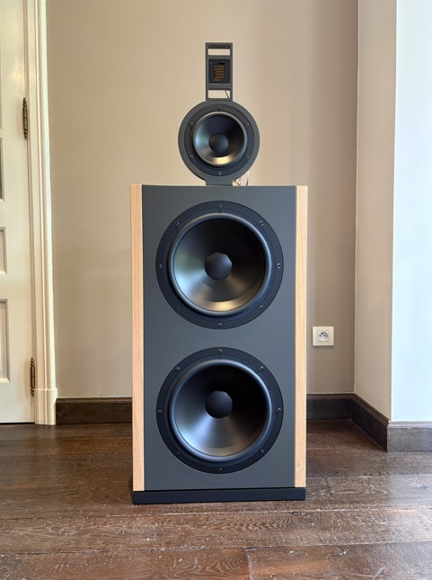
The VCL DI-3212-P is the 3-way version of the VCL DI-4212-P. By removing the dedicated midwoofer section, a more compact and lower cabinet design is achieved while preserving the core acoustic philosophy of the larger model.
The DI-3212-P uses the same premium Audio Technology woofers and midrange driver, combined with the Mundorf tweeter, all mounted in the same optimized baffles as the DI-4212-P.
This design makes it possible to directly compare the sonic performance of a high-end 3-way concept with its 4-way counterpart, the DI-4212-P.
Extensive listening tests and technical experiments were carried out using various crossover filter topologies to further refine the system performance.
Besides different digital filter types, also an analog LR2 passive crossover filter has been designed.
Detailed results, listening impressions, and technical insights on the DI-3212-P will be published soon.
Contents
- Chapter 1 Specification headlines
- Chapter 2 Cabinet
- Chapter 3 Transducers
3.1 – Woofer Audio Technology Flex 12 D 77
3.2 – Midrange Audio Technology C-Quenze 18 H 52
3.3 – Tweeter Mundorf AMT17D2.2 - Chapter 4 Dipole radiation simulation of the transducers on their baffle
4.1 – Woofer dipole radiation
4.2 – Midrange dipole radiation
4.3 – Tweeter AMT dipole radiation - Chapter 5 Acoustical measurements of the transducers in the dipole baffle
5.1 – Woofer on axis ground plane measurements
5.2 – Midrange and tweeter on axis full space measurements
5.3 – Woofer off axis ground plane measurements
5.4 – Midrange off axis full space measurements
5.5 – Tweeter off axis full space measurements - Chapter 6 Crossover filter
6.1 – Digital Crossover design using measurement results
6.2 – Passive Crossover design using measurement results - Chapter 7 New experiences and insights
- Chapter 8 Gallery
Chapter 1 Specification Headlines
- System: 3-way full range dipole with a active digital and passive X-over
- Woofer: 2 x Audio Technology 12 D 77 customized
- Midrange: Audio Technology C-Quenze 18 H 52 06 13 SDKA LR
- Tweeter: Mundorf AMT17D2.2
- Low frequency response: F3 = 35 Hz
- Sensitivity: 81 dB at 1m, 2.83 Vrms, full space
- SPL at maximum excursion of the woofers at 35 Hz @ 35 – 20000 Hz: 98 dB, 1m, full space
- Crossover: Different DSP filter types at 250 and 2500 Hz; passive LR2 filter at 250 and 3200 Hz
- Dimensions: width x heigth x depth = 46 cm x 116 cm x 34 cm
Chapter 2 Cabinet
Cabinet sketch
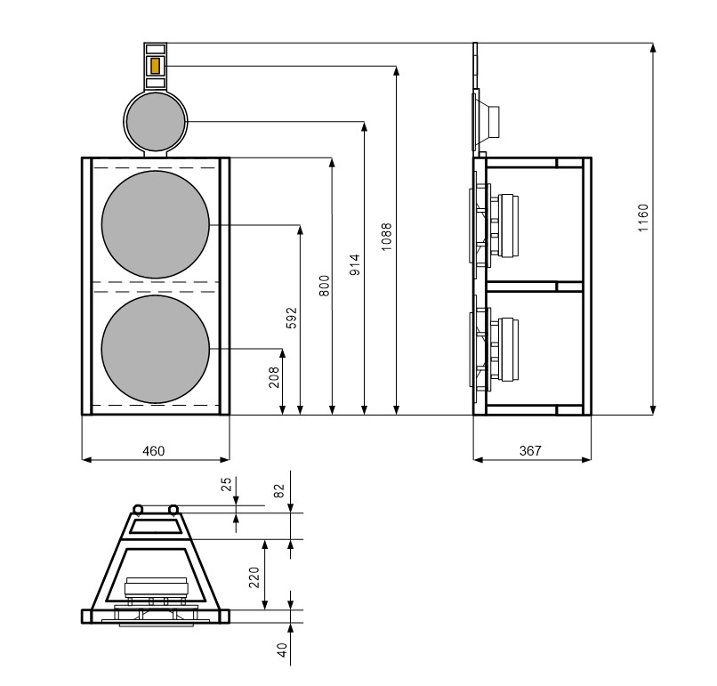
The woofers baffle measures 80 x 40 cm. The midrange and tweeter baffles are mounted on the woofer baffle.
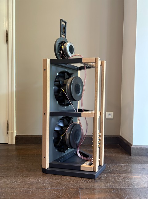
To assemble the speaker as a single unit, trapezoidal frames and a vertical pole are used. The trapezoidal frames are screwed to the back of the woofer baffle and to the vertical pole at the back. On the sides, two side panels are screwed to the woofer baffle. This creates a standing structure with the woofer baffle at the front and the vertical pole at the back.
Chapter 3 Transducers – Acoustical measurements on IEC baffle
Audio Technology transducers are used for the woofers and the midrange. We have had excellent experiences with these drivers in past projects. They perform exceptionally well and are very solidly and reliably built. Additionally, their Flex units allow the driver parameters to be customized for a dipole application, a feature offered by very few speaker manufacturers.
For the tweeter, we opted for a Mundorf AMT tweeter. We are familiar with the Mundorf from our previous dipole project, the VCL DI-215-W.
For all new speaker drivers used in a new project, we measure them on our IEC 225 Hz baffle. The SPL on-axis at a distance of 1 meter and 2.83 Vrms is measured, as well as the impedance at 2.83 Vrms. Using these two measurements, it is possible to create a fairly accurate infinite baffle response of the driver, which is used in the further design process.
With the IEC 225 Hz baffle, the SPL can be accurately measured above 650 Hz without diffraction. The SPL below 650 Hz is calculated from the impedance measurement and the other TSP (Thiele-Small parameters). Both SPL responses are then spliced together to achieve the infinite baffle response.
3.1 – Woofer Audio Technology Flex 12 D 77
For the woofer selection, we started with an existing Audio Technology Flexunit, the 12 D 77 25 10 KAP. We adjusted several parameters to increase the Qts and achieve maximum sensitivity with the existing D magnet for a dipole application. Additionally, we opted for an underhung voice coil for this woofer. The voice coil resistance was slightly increased to allow two woofers to be connected in parallel for this project.
Audio Technology Flex 12 D 77 mounted in IEC baffle

Audio Technology Flex 12 D 77 (custom) – Measured Infinite Baffle response at 1m on-axis , 2.83 Vrms

Audio Technology Flex 12 D 77 (custom) – Measured Impedance at 2.83 Vrms on IEC baffle

3.2 – Midrange Audio Technology C-Quenze 18 H 52
For years, we have been using the Audio Technology Flex 5 H 52 17 06 SD midwoofer in a 3-way speaker with excellent results.
The Audio Technology C-Quenze 18 H 52 06 13 SDKA LR, which we are choosing for this project, features a Kapton Aluminum underhung voice coil and the LR-magnet system. It is highly recommended by Audio Technology for dipole applications, and Troels Gravesen calls it “My favorite midrange.”
Audio Technology C-Quenze 18 H 52 06 13 SDKA LR mounted in IEC baffle

Audio Technology C-Quenze 18 H 52 06 13 SDKA LR – Measured Infinite Baffle response at 1m on-axis , 2.83 Vrms

Audio Technology C-Quenze 18 H 52 06 13 SDKA L – Measured Impedance at 2.83 Vrms on IEC baffle

3.3 – Tweeter Mundorf AMT17D2.2
We have chosen for this project the Mundorf AMT17D2.2. This dipole tweeter is performing wery well in the VCL DI-215-W and is one of the smallest dipole AMT tweeters that can be found.
Mundorf AMT17D2.2 mounted in IEC baffle

Mundorf AMT17D2.2 – Measured Infinite Baffle response at 1m on-axis , 2.83 Vrms

Mundorf AMT17D2.2 – Measured Impedance at 2.83 Vrms on IEC baffle

Chapter 4 Dipole radiation simulation of the transducers on the baffle
4.1 – Woofer dipole radiation
Simulation in Leap
2 x Audio Technology 12D77 on a baffle with dimensions W x H = 540 x 880 mm. The baffle width for the Leap simulation is calculated as the actual baffle width of 460 mm plus two times the baffle depth of 40 mm.

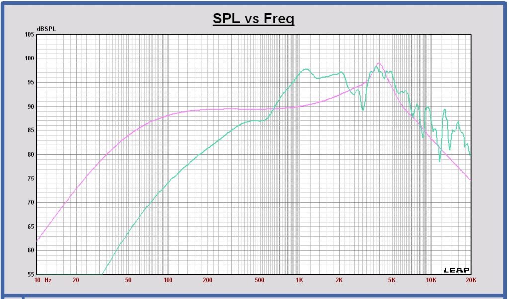
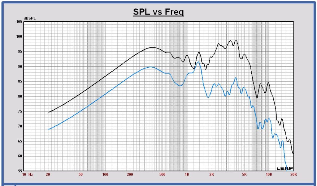
SPL on axis (black) and SPL on infinite baffle (pink) at 3m, 2.83 Vrms in full space

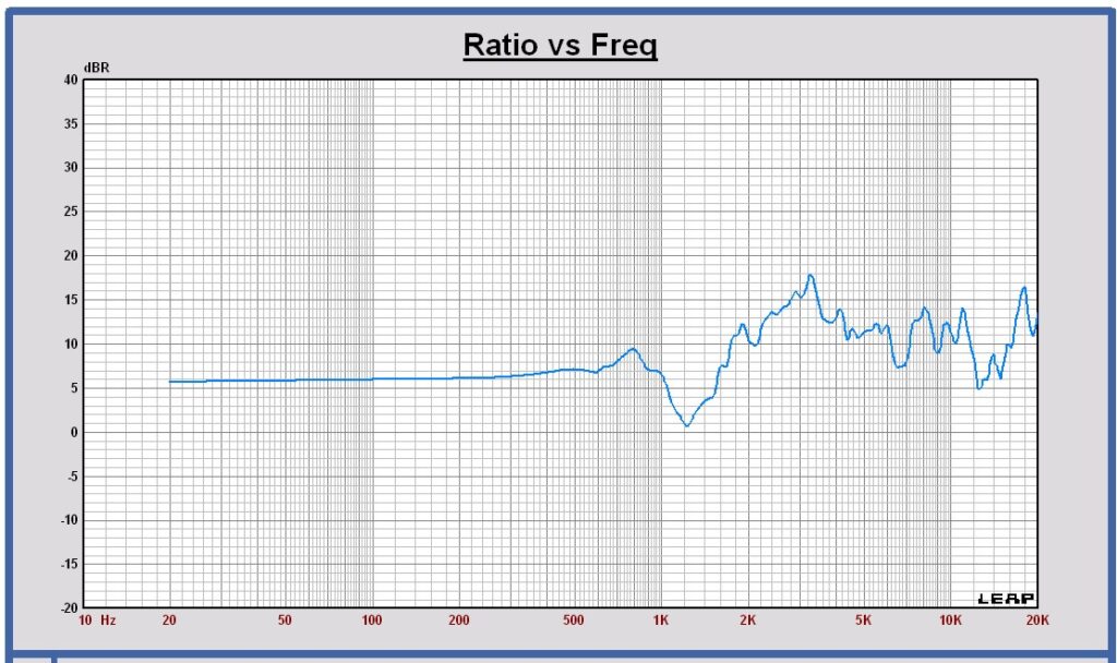
Dipole transfer (blue) compared with +6 dB slope curve (yellow)

The dipole transfer is the ratio of the SPL on axis over the SPL on infinite baffle. In normal conditions this dipole transfer is a +6dB slope below the dipole peak.
The deviation of the dipole transfer below 80 Hz is caused by a Leap artifact at low frequencies. Some correction can be calculated on the dipole transfer below 80 Hz. The corrected dipole transfer is shown in the plot below.
Corrected dipole transfer up to 80 Hz (violet) compared with +6 dB slope curve (yellow) and the uncorrected simulated dipole transfer (blue)

Using this corrected dipole transfer together with the woofer infinite baffe response, the SPL on axis response at 1m, 2.83 Vrms can be calculated. It isexpected to be more accurate and closer to the practical SPL, that will be measured.
Corrected SPL on axis (black) using corrected dipole transfer and SPL on infinite baffle (pink) at 1m, 2.83 Vrms in full space

This SPL curve can be used to make the loudspeaker sensitivity analysis.
Choosing F3 = 35 Hz, it is expected that the sensitivity at 1m,2.83 Vrms in full space will be close to 81 dB.
SPL on axis and horizontal off axis 15 30 45 60 75 90 degrees at 3m, 2.83 Vrms in full space

Horizontal polar diagram 80 – 160 – 320 – 640 – 1280 Hz at 3m in full space

SPL on axis and vertical off axis 15 30 45 60 75 90 degrees at 3m, 2.83 Vrms in full space

Vertical polar diagram 80 – 160 – 320 – 640 – 1280 Hz at 3m in full space

SPL on axis and the power H+V (blue), H (orange) and V (violet) at 3m, 2.83 Vrms in full space

Directivity Index H+V (blue), H (orange) and V (violet) at 3m in full space

Dipole beaming
If we examine the DI (directivity index) curves of this dipole system, we see that the DI increases above a certain frequency, or in other words, the directivity of the driver in the dipole baffle increases at higher frequencies. This directivity is caused, on the one hand, by the dipole effect and, on the other hand, by the driver’s directivity at higher frequencies. The dipole directivity starts at low frequencies and decreases toward higher frequencies, depending on the baffle width, which determines the path length from the rear to the front side of the dipole system.
It would be interesting to observe only the effect of dipole directivity as a function of frequency, excluding the driver’s directivity. The dipole directivity can be calculated by dividing the total DI by the DI caused by the driver’s directivity. In the plot below, the total DI is shown along with the DI resulting from the driver’s directivity and the DI resulting from the dipole directivity.
Directivity Index H+V (blue), driver directivity on infinite baffle (grey) and dipole driectivity (pink)

4.2 – Midrange dipole radiation
Simulation in Leap
Audio Technology 18 H 52 06 13 SDKA-LR on a circular baffle with diameter of 246 mm and 18 mm depth. The baffle diameter for the Leap simulation is calculated as the actual baffle diameter of 210 mm plus two times the baffle depth of 18 mm, which equals 246 mm.

SPL on axis (black) and SPL on infinite baffle (pink) at 3m, 2.83 Vrms in full sphere

Dipole transfer (green) compared with +6 dB slope curve (orange)

SPL on axis and off axis 15 30 45 60 75 90 degrees at 3m, 2.83 Vrms in full sphere

Polar diagram 320 – 640 – 1280 – 2560 – 3840 Hz at 3m in full sphere

SPL on axis (black) and the power (green) at 3m, 2.83 Vrms in full sphere

Directivity Index (green) at 3m in full sphere

Directivity Index H+V (green), driver directivity on infinite baffle (grey) and dipole directivity (pink)

4.3 – Tweeter AMT dipole radiation
Simulation in Leap
Mundorf AMT17D2.2 on a baffle with dimensions W x H x D = 70 x 80 x 12 mm. For the Leap simulation a box with same dimensions is choosen with two drivers in opposite phase, one on the front and one on the back. A box with some depth is preferred as baffle model to obtain the best diffraction simulation at a few kHz.

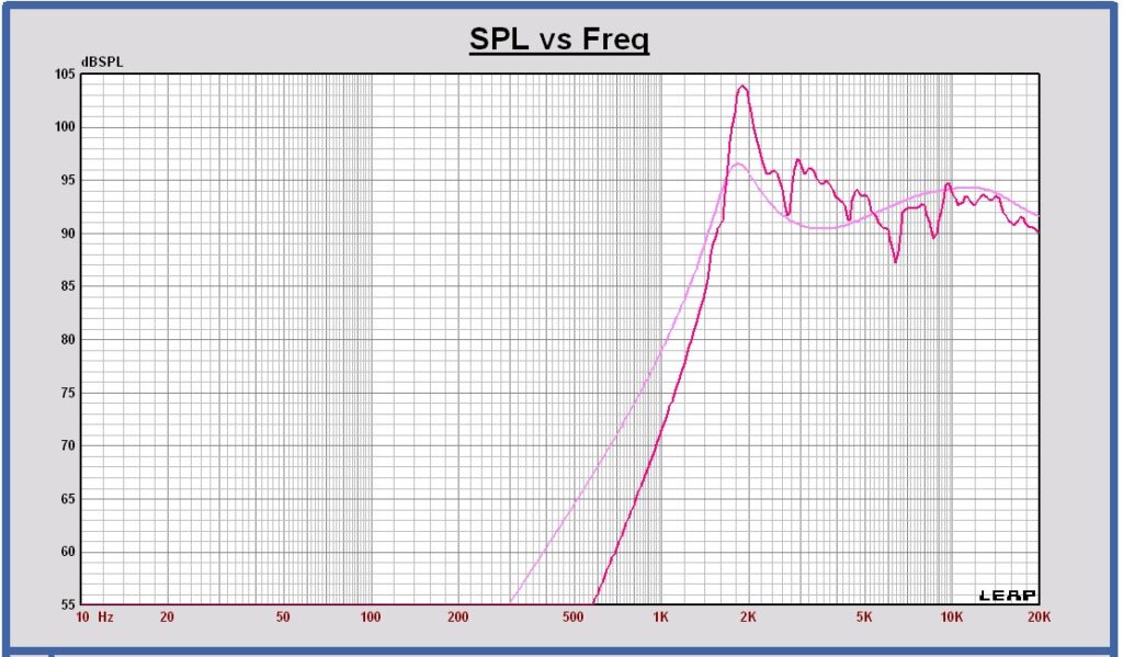
SPL on axis (black) and SPL on infinite baffle (pink) at 3m, 2.83 Vrms in full sphere

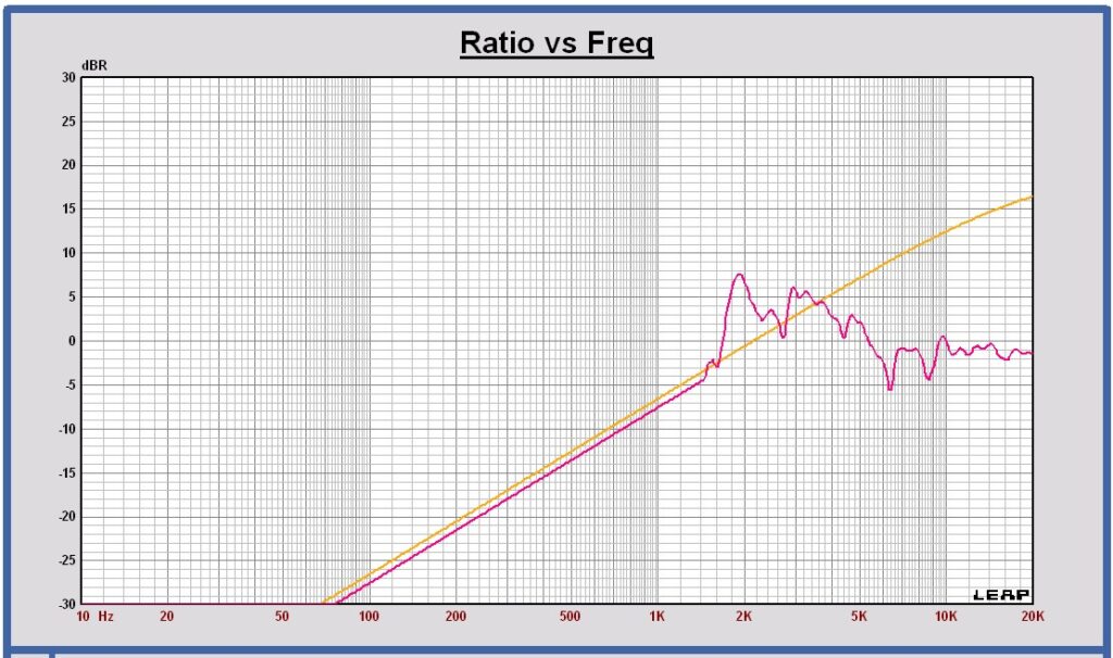
Dipole transfer (red) compared with +6 dB slope curve (yellow)

SPL on axis and horizontal off axis 15 30 45 60 75 90 degrees at 3m, 2.83 Vrms in full sphere

Horizontal polar diagram 1.20 – 2.56 – 3.84 – 5.12 – 6.40 – 12.80 kHz at 3m in full sphere

SPL on axis and vertical off axis 15 30 45 60 75 90 degrees at 3m, 2.83 Vrms in full sphere

Vertical polar diagram 1.20 – 2.56 – 3.84 – 5.12 – 6.40 – 12.80 kHz at 3m in full sphere

SPL on axis and the power H+V (red), H (orange) and V (violet) at 3m, 2.83 Vrms in full sphere

Directivity Index H+V (red), H (orange) and V (violet) at 3m in full sphere

Directivity Index H+V (red), driver directivity on infinite baffle (grey) and dipole directivity (pink)

Chapter 5 Acoustical measurements of the transducers in the dipole baffle
For this 3-way version again acoustic measurements were performed indoors. As the 3-way cabinet is different around midrange and tweeter, the measurements were done again.
The woofers were measured ground plane at a distance of 2 m, and the midrange and the tweeter in full space at 1 m. The on-axis SPL measurements are corrected for low frequencies using simulation results. The off-axis measurements are used to calculate the room power and the directivity index.
5.1 – Woofer on axis ground plane measurements
Measured SPL of the woofers at 2m, 2.83 Vrms ground plane (equal to 1m full space) in blue color
SPL of the woofers on infinite baffle at 1m, 2.83 Vrms in pink color

Below 50 Hz a measurement correction has been applied for the dipole transfer being +6 dB/octave at low frequencies.
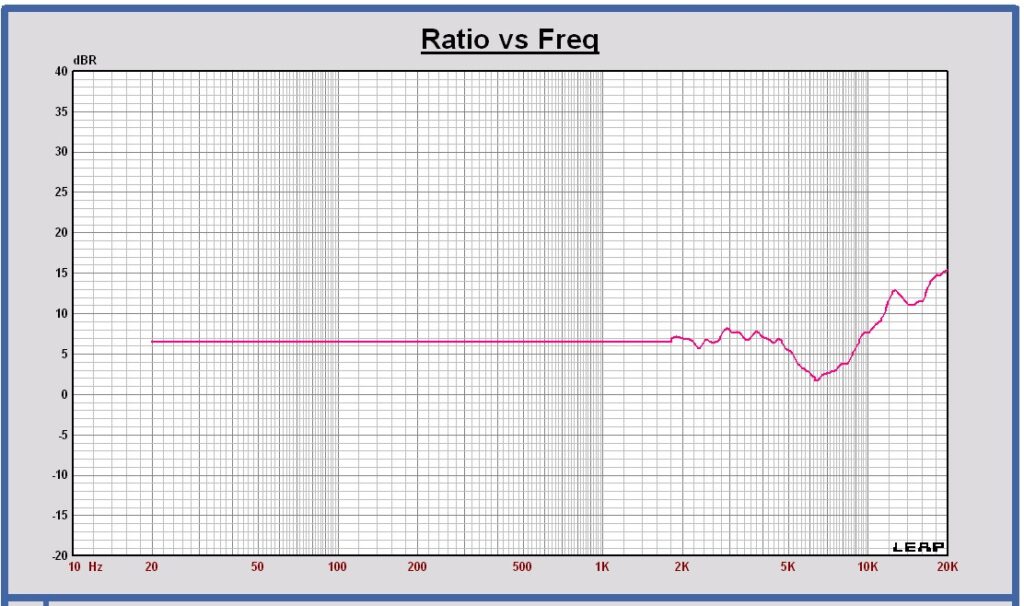
Woofer dipole transfer in full space in blue and the + 6 dB transfer in yellow

5.2 – Midrange and tweeter on axis full space measurements
Measured SPL of the midrange at 1m, 2.83 Vrms full space in green color
SPL of the midrange on infinite baffle at 1m, 2.83 Vrms in pink color
Below 280 Hz a measurement correction has been applied for the dipole transfer being +6 dB/octave at low frequencies.
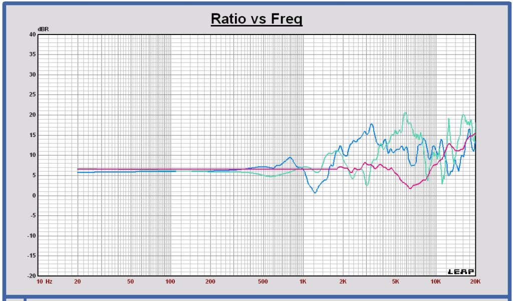
Midrange dipole transfer in full space in green and the + 6 dB transfer in yellow

Measured SPL of the tweeter at 1m, 2.83 Vrms full space in red color
SPL of the tweeter on infinite baffle at 1m, 2.83 Vrms in pink color
Below 1400 Hz a measurement correction has been applied for the dipole transfer being +6 dB/octave at low frequencies.
Tweeter dipole transfer in full space in red and the + 6 dB transfer in yellow
5.3 – Woofer off axis ground plane measurements
The off axis woofers SPL curves are measured with a ground plane measurement at 2 m distance. The baffle is placed perpendicular to the ground, in a way the vertical off axis angle is – 12 degrees and not 0 degrees. The SPL deviation is minimal with this vertical angle offset. The SPL curves can be used to evaluate the SPL off axis behavior and to calculate the power response and the directivity index.
Measured horizontal off axis SPL of the woofers at 2m, 2.83 Vrms ground plane (levels re-calculated to 1m full space)
at 0, 15, 30, 45, 60, 75 and 90 degrees

Measured horizontal off axis SPL of the woofers at 2m, 2.83 Vrms ground plane (levels re-calculated to 1m full space)
at 180, 165, 150, 135, 120, 105, and 90 degrees
Measured woofer SPL on axis (black) and the power (blue) at 1m, 2.83 Vrms in full space
Power calculated with the woofers horizontal off axis measurements only
Directivity Index of the woofers in full space, calculated with the woofers horizontal off axis measurements only
5.4 – Midrange off axis full space measurements
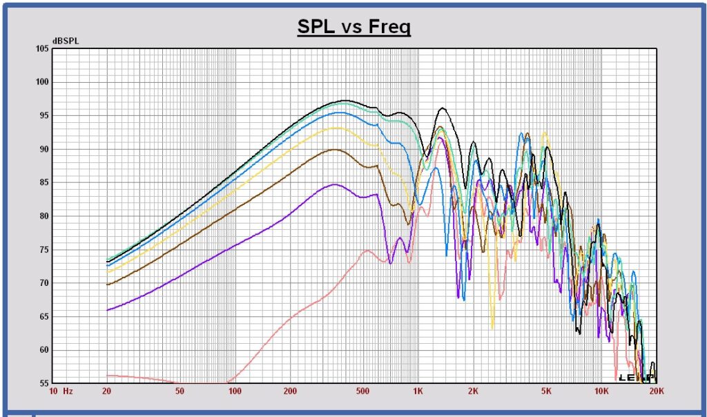
Measured horizontal off axis SPL of the midrange at 1m, 2.83 Vrms in full space
at 0, 15, 30, 45, 60, 75 and 90 degrees

Measured horizontal off axis SPL of the midrange at 1m, 2.83 Vrms in full space
at 180, 165, 150, 135, 120, 105, and 90 degrees

Measured midrange SPL on axis (black) and the power (green) at 1m, 2.83 Vrms in full space.
Power calculated with the midrange horizontal off axis measurements only
Directivity Index of the midrange in full space, calculated with the midrange horizontal off axis measurements only

5.5 – Tweeter off axis full space measurements
Measured horizontal off axis SPL of the tweeter at 1m, 2.83 Vrms in full space
at 0, 15, 30, 45, 60, 75 and 90 degrees
Measured horizontal off axis SPL of the tweeter at 1m, 2.83 Vrms in full space
at 180, 165, 150, 135, 120, 105, and 90 degrees

Measured tweeter SPL on axis (black) and the power (red) at 1m, 2.83 Vrms in full space.
Power calculated with the tweeter horizontal off axis measurements only

Directivity Index of the tweeter in full space, calculated with the tweeter horizontal off axis measurements only
Chapter 6 Crossover filter
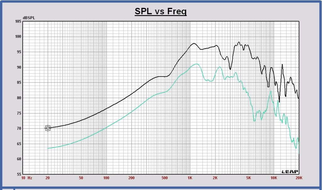
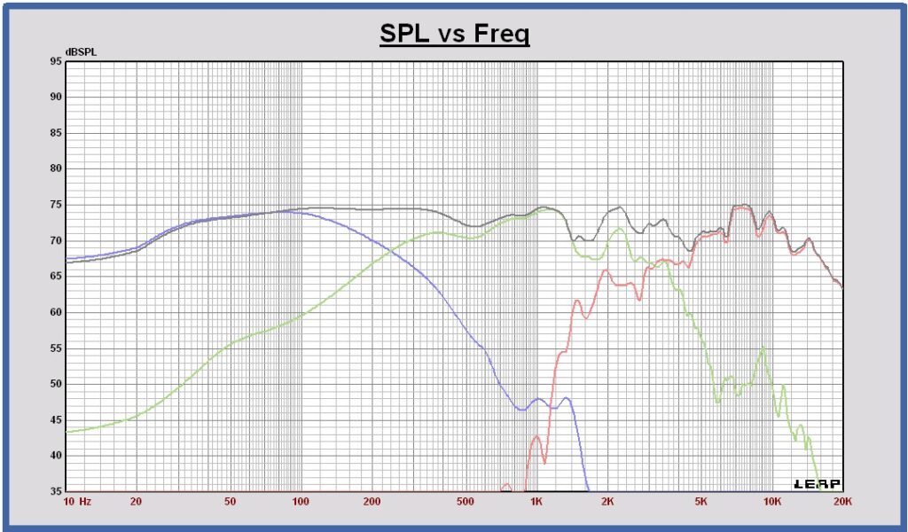
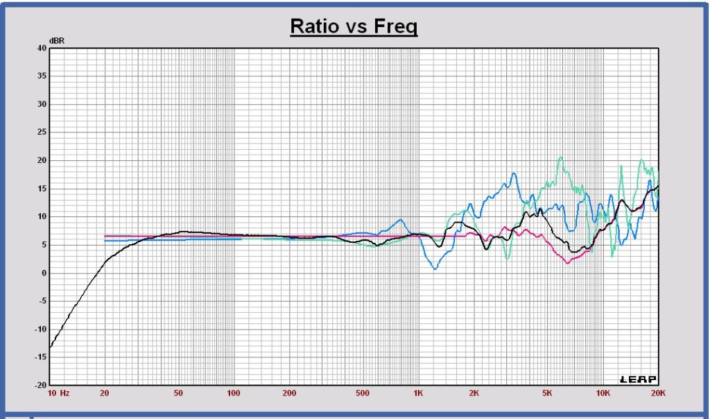
Measured SPL responses of all drivers in the dipole baffles at 1m, 2.83 Vrms in full space
woofer = blue, midrange = green and tweeter = red

Measured DI responses of all drivers in the dipole baffles at 1m in full space
woofer = blue, midrange = green and tweeter = red
6.1 – Digital Crossover design using measurement results
A digital crossover filter has been designed to do an initial evaluation of the behavior of the sum of the filtered drivers of this dipole speaker – both the on-axis and off-axis SPL response – the power response and the directivity index. An LR4-type filter was chosen because it provides an interesting reference point to start with and to compare with other filter types at a later stage.
The crossover frequencies are chosen at 250 Hz and 2500 Hz. This ensures that the individual driver DI curves have sufficient overlap to achieve the flattest overall DI value for the summed response of this dipole speaker.
Crossover filter targets LR4 250 2500 Hz
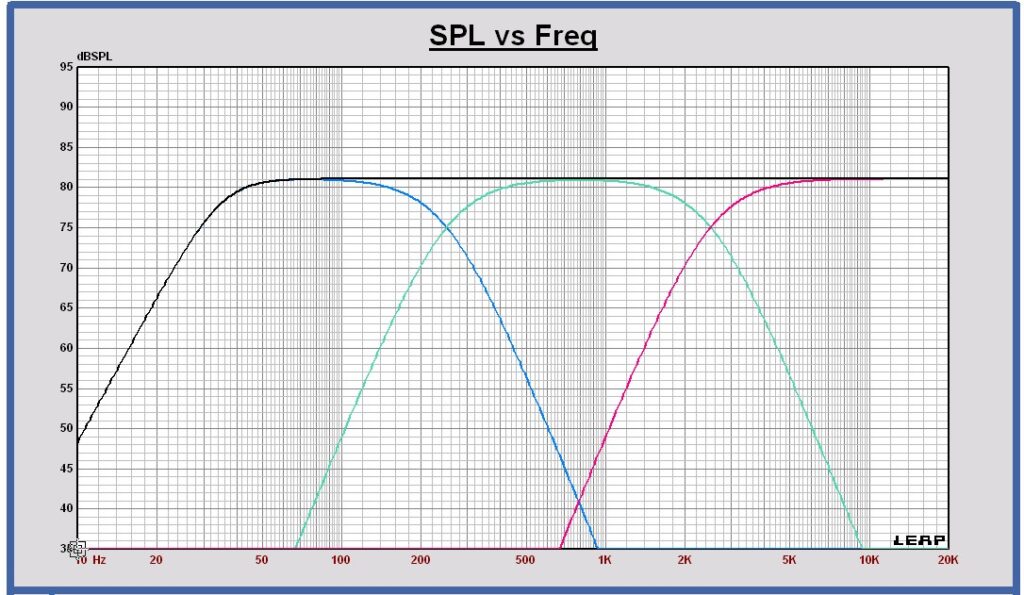
SPL on axis of the filtered drivers and the sum at 1m, 2.83 Vrms in full space
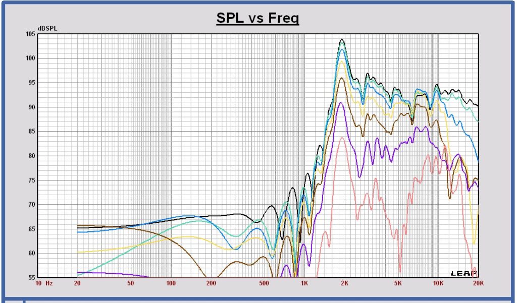
SPL horizontal off axis of the sum at 0 , 15, 30, 45, 60, 75 and 90 degrees at 1m, 2.83 Vrms
Normalized to the 0 degrees on axis response.

This SPL off axis graph is not correct below 200 Hz. The SPL off axis responses are measured indoors and below 200 Hz the measured responses are affected by room reflections.
Power response of the filtered drivers and the sum in free space at 1m, 2.83 Vrms in full space

Directivity Index in free space of the filtered drivers and the sum
woofer = blue, midrange = green and tweeter = red
As expected, the power and DI responses show that the midrange has less power above 1kHz. This is caused by the driver itself beaming at those frequencies. We have decided to start with the 6.5-inch Audio Technology midrange, check it all with measurements and listen to it. Potentially we do additional tests later with other midranges, including smaller versions.
6.2 – Passive Crossover design using measurement results
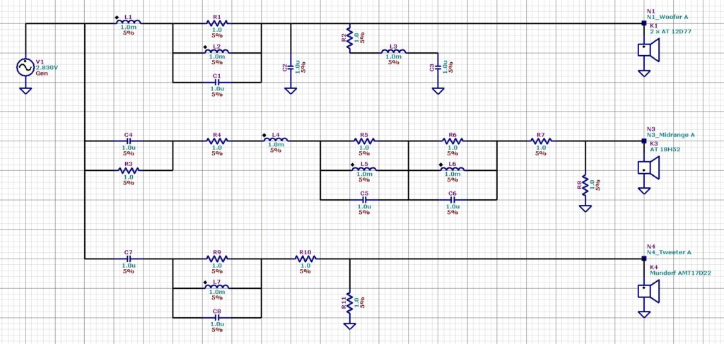
Using the SPL and impedance measurements performed, a passive crossover filter has been designed. To make the crossover schematic not too complex, a Linkwitz – Riley 2nd order type filter has been chosen.
Crossover filter targets LR2 250 3200 Hz
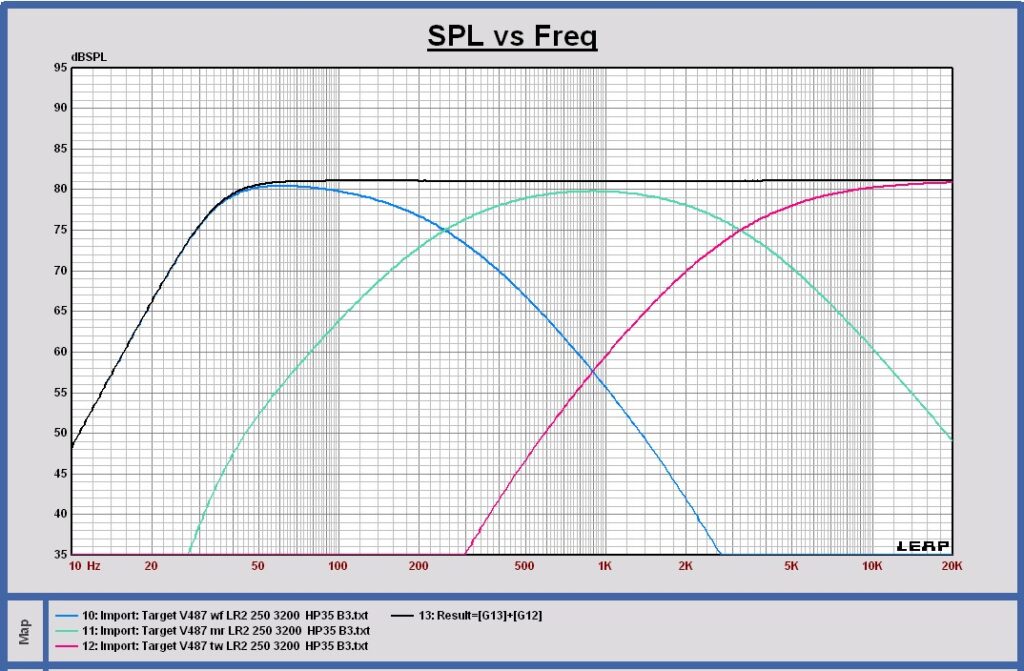
Sensitivity 81 dB; F3 = 35 Hz
Crossover filter schematic configuration
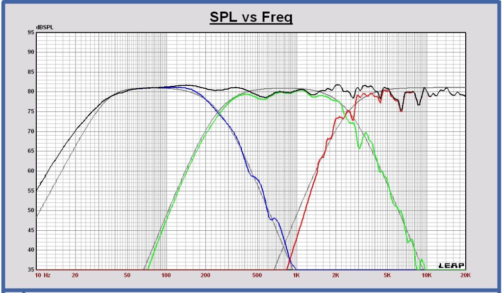
SPL on axis of the filtered drivers and the sum at 1m, 2.83 Vrms in full space

Impedance

SPL horizontal off axis of the sum at 0 , 15, 30, 45, 60, 75 and 90 degrees at 1m, 2.83 Vrms

Power response of the filtered drivers and the sum in free space at 3m, 2.83 Vrms in full space
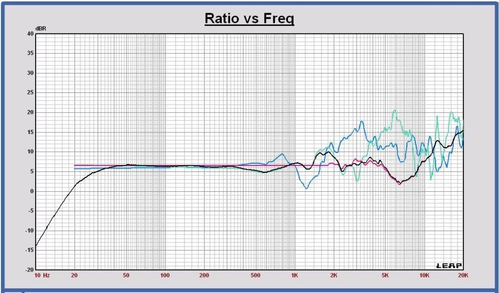
Directivity Index in free space of the filtered drivers and the sum
sum = black, woofer = blue, midrange = green and tweeter = red
Chapter 7 New experiences and insights
Note: this chapter will be published soon.