2-way monitor with Purifi midwoofer and 2 x Purifi passive radiator; Scanspeak Be tweeter

With this Purifi transducer combination, one active and two passive transducers, a high acoustical output down to low frequencies can be realized in a small cabinet. The moving mass Mms of the active driver is relative high (26.4 g) and the compliance Cms low to obtain the low free air resonance fs (30 Hz), and that combined with the large maximum linear excursion of the transducers, makes it possible. Frequency F3 (-3dB SPL frequency value) will become 38 Hz and the SPL at maximum excursion will be 98 dB at 1m distance in free space.
Contents
- Specification Headlines
- Speaker System
- Cabinet
- SPL and impedance curves of the transducers in the cabinet
- Off axis response, Power and Directivity Index of the transducers in the cabinet
- Crossover Filter
Specification Headlines
- System: 2-way, passive radiator system, analog X-over
- Midwoofer: Purifi PTT6.5W04-01A
- Tweeter: Scanspeak D3004-664000
- Passive Radiator: 2 x Purifi PTT6.5PR-01A
- Low frequency response: F3 = 38 Hz
- Sensitivity: 81 dB at 1m, 2.83 Vrms, full space
- SPL at maximum excursion, 38 – 20000 Hz: 98 dB, 1m, full space
- Crossover: LR4 at 2500 Hz or Elliptical 3rd order at 2500 Hz
- Impedance: mean value between 4 and 8 Ohm
- Cabinet dimensions: width x heigth x depth = 24 cm x 42 cm x 38 cm
Speaker System
Transducers
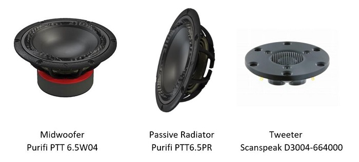
Purifi PTT6.5W04-01A, Purifi PTT6.5PR-01A, Scanspeak D3004-66400
The Purifi woofer is known for its very low surround radiation and magnetic hysteresis distortion, low BL modulation and a “real” long-stroke behavior. The passive radiator is equipped with the same suspension and is also long-stroke.
The Scanspeak tweeter has a Beryllium cone, a well known transducer used in high-end speakers.
Passive Radiator System – Small Signal Analysis
A Purifi 6.5 inch midwoofer, provided with two 6.5 inch Purifi passive radiators, one on each side wall, is used in this 2 way speaker.
As a reference to calculate the responses of the passive radiator system, the article “Passive-Radiator Loudspeaker Systems” by Richard H.Small is used. In this post only the parameter values and the calculation results are summarized. For a more detailed understanding, the reference article can be used.
For the Purifi midwoofer: fs = 30 Hz; Vas = 26 L; Qts = 0.29
For the Purifi passive radiator: Vap = 27.3 L
For a cabinet volume = 15 L, fp = 17 Hz (total cone mass for both passive radiators together adjusted to 160 g), no cabinet filling and a serial source resistance of 0.5 Ohm
Then: Ts = 5.3 ms; Tp = 9.4 ms; alfa = 1.73; delta = 3.64; QT = 0.34
With the above parameter values, the frequency response on infinite baffle can be calculated, using the formula as mentioned in the reference article.

The green curve shows the passive radiator response, the red curve a Butterwoth B4 response at the same system frequency to compare with. F3 = 34.5 Hz with these parameter values.
Remark that these responses are a result with low losses, but the calculated responses are already indicative.
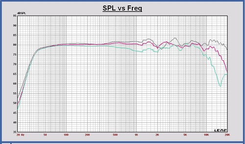
Simulating the frequency response on infinite baffle in Leap with the same parameters, is shown in the next graph. The results are comparable.
As a first conclusion of this passive radiator system study, the cabinet volume can be chosen 15 L and the total mass of each passive radiator cone 80 gram. These values can be fine tuned during the prototype measurements.
Cabinet
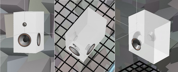
Cabinet dimensions

3-D look in Leap
SPL and impedance curves of the transducers in the cabinet
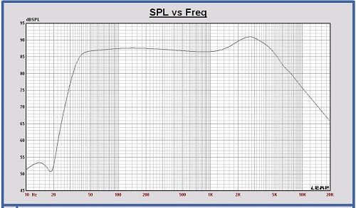
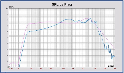
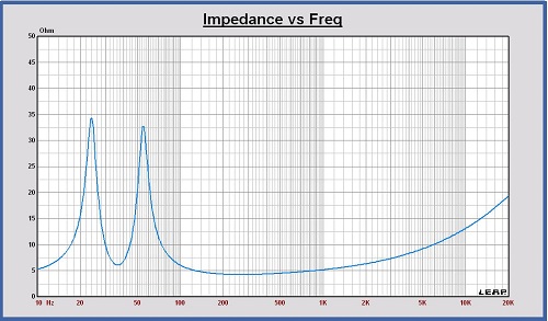
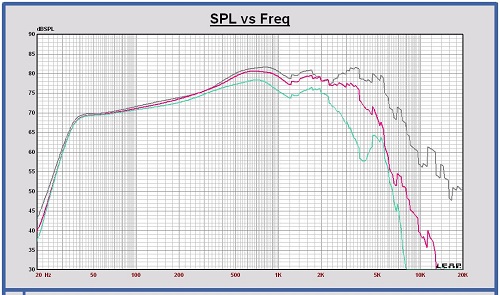
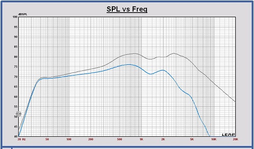
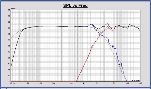
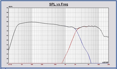
These are the SPL and impedance curves of the transducers placed in the cabinet in free space at 1 meter, 2.83 Vrms . Also the SPL responses on infinite baffle are shown to see the impact of the cabinet shape on the response.
These simulated curves will be used for a first crossover filter design.
SPL Purifi PTT 6.5W04 and 2 x Purifi PTT 6.5PR in the cabinet in free space (blue curve) and on infinite baffle (pink curve)
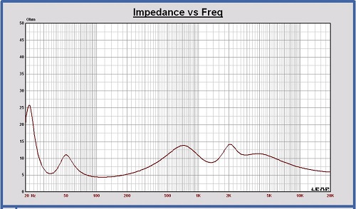
Impedance Purifi PTT 6.5W04 and 2 x Purifi PTT 6.5PR in the cabinet
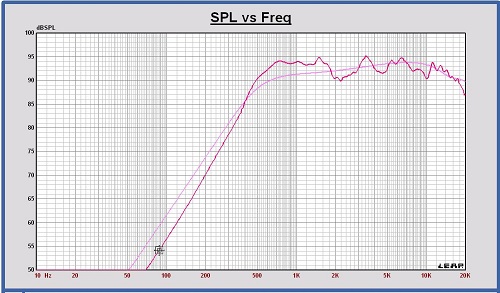
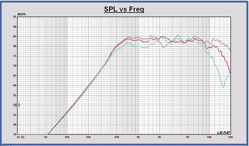
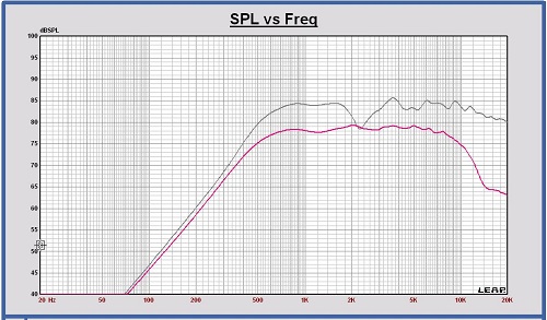
SPL Scanspeak D3004-664000 in the cabinet in free space (red curve) and on infinite baffle (pink curve)
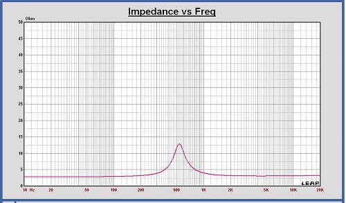
Impedance Scanspeak D3004-664000
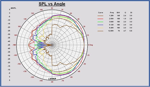
Horizontal polar diagram Scanspeak D3004-664000 in cabinet free space at 1.2 – 2.5 – 3.8 – 5.1 – 6.4 – 12.8 kHz
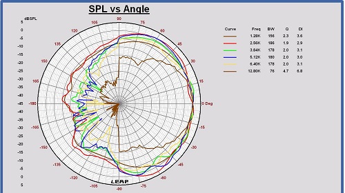
Vertical polar diagram Scanspeak D3004-664000 in cabinet free space at 1.2 – 2.5 – 3.8 – 5.1 – 6.4 – 12.8 kHz
Off axis response, Power and Directivity Index of the transducers in the cabinet
To choose the optimum crossover frequency for this speaker, the horizontal and vertical SPL off axis responses of midwoofer and tweeter have been simulated in steps of 15 degrees, the speaker placed in full sphere at 3m distance. The power is calculated out of the mean value of all these curves. In this case, the power is represented as the SPL of an omnidirectional source at 3m distance in full sphere with a SPL value equal to the power.
Horizontal SPL off axis response of the midwoofer in the cabinet at 0, 30 and 60 degrees
Horizontal SPL off axis response of the tweeter in the cabinet at 0, 30 and 60 degrees
SPL on axis and Power of the midwoofer in the cabinet in full sphere
SPL on axis and Power of the tweeter in the cabinet in full sphere
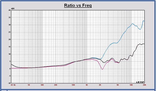
Directivity Index DI in full sphere of the midwoofer and tweeter in the cabinet
The Directivity Index plot shows that, to keep the DI of the sum response flat, the crossover frequency must be located around 2.5 kHz.
Crossover Filter
Targets Crossover Filter LR4 at 2500 Hz
Crossover filter schematic configuration
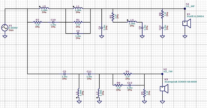
Impedance with crossover flter
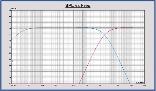
SPL of the filtered drivers and the sum at 1m, 2.83 Vrms
SPL off axis of the filtered drivers and the sum at 1m, 2.83 Vrms
Power response of the filtered drivers and the sum in full space at 1m, 2.83 Vrms
The mutual distance between the drivers in vertical direction is not included in this calculation. With this distance included, an extra power dip at the crossover frequency will appear with a DI peak as a consequence.
Directivity Index in full sphere of the filtered drivers and the sum