3-way full range dipole speaker with Peerless woofers, Audio Techology midrange and Mundorf AMT dipole tweeter

- The VCL EX21 is a full range dipole loudspeaker. Dipoles have radiating surfaces at the front and back side of the cabinet that are operating in anti phase. They don’t have an omnidirectional radiation pattern, but two symmetrical lobes at the front and back side of the cabinet. In this way dipoles have less room power for the same SPL on axis than omnidirectional loudspeakers. Because the radiation pattern around the loudspeaker is the same for all frequencies, the radiated power is constant versus frequency.
Most commercial loudspeakers are monopole designs, a single transducer or transducer system is used. This type of loudspeaker is omnidirectional at low frequencies and unidirectional (cardïode) at medium and high frequencies. Because of this changing radiation pattern the power is not constant versus frequency, it is about 6 dB higher at low frequencies for a flat SPL on axis. - Because dipole loudspeakers have less room power and a flat power versus frequency, they are less sensitive for room acoustics than monopole loudspeakers.
- To optimize the frequency response at the loudspeaker backside and to avoid low frequency cavity resonances, a symmetrical woofer setup is chosen at the front and the back side, 3 woofers at each side. With this symmetrical multidriver setup harmonic distortion and SPL headroom are improved. The midrange and the tweeter are single units and mounted on a small flat baffle.
- The transducers are six 10 inch woofers, three on the front panel and three on the back panel, a 6.5 inch midrange and an AMT dipole tweeter. Peerless SLS 10 – P830668 woofers, Audio Technology CQuenze 18 cm midrange and Mundorf AMT17D2.2 tweeter.
- The speaker cabinet is 120 cm high, 54 cm wide and 20 cm deep.
- The speaker sensitivity is 82 dB at 1m, 2.83 Vrms, full space, the low frequency response F3 = 45 Hz and for a woofer maximum excursion condition at 45 Hz the speaker maximum SPL is 98 dB @ 45 – 20000 kHz at 1m, free space.
Contents
- Specification Headlines
- Estimation Bill Of Material
- Transducers
- Cabinet
- Dipole radiation behavior of the transducers in the cabinet
- Woofer Dipole
- Midrange Dipole
- Tweeter Dipole
- Crossover filter
- Maximum excursion and maximum SPL with crossover filter
Specificaton Headlines
- System: 3-way full range dipole, analog X-over
- Woofer: 6 x Peerless SLS-P830668
- Midrange: Audio Technology CQuenze 18 cm
- Tweeter: Mundorf AMT17D2.2
- Low frequency response: F3 = 45 Hz
- Sensitivity: 82 dB at 1m, 2.83 Vrms, full space
- SPL at maximum excursion, 45 – 20000 Hz: 98 dB, 1m, full space
- Crossover: Linkwitz – Riley 4th order at 300 and 2700 Hz
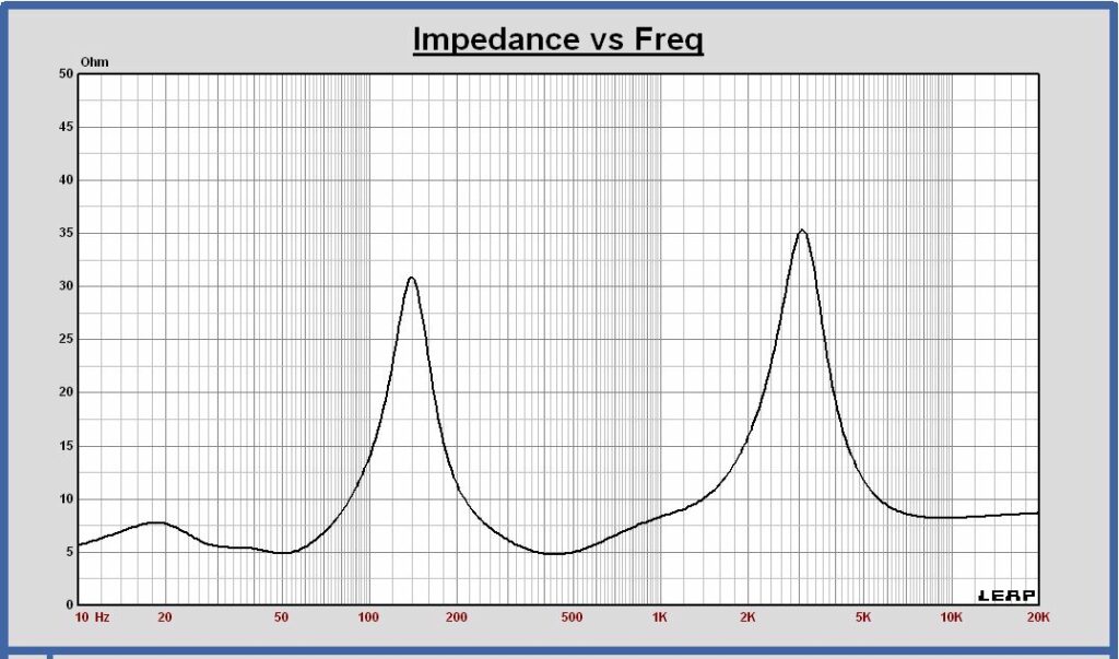
- Impedance: mean value between 5 and 35 Ohm
- Cabinet dimensions: width x heigth x depth = 54 cm x 120 cm x 20 cm
Estimation Bill Of Material
- 12 x Woofer Peerless SLS-P830668: 888 euro
- 2 x Midrange Audio Technology CQuenze 18 cm: 598 euro
- 2 x Tweeter Mundorf AMT17D2.2: 538 euro
- Components high quality crossover: 800 euro
- Components medium quality crossover: 500 euro
- Cabinet material: 100 euro
- Cabinet Accessoires: 100 euro
- Total with high quality crossover 3024 euro
- Total with medium quality crossover 2724 euro
Transducers

Peerless SLS-P830668, Audio Technology CQuenze 18 cm, Mundorf AMT17D2.2
The Peerless SLS-P830668 is a 10 inch woofer that can be used in a dipole speaker system. The maximum linear excursion is 8.3 mm peak. Q-factor Qts = 0.55. This driver is specially designed to produce low noise at low frequencies in an open baffle.
The Audio Technology CQuenze 18 cm is a 6.5 inch midrange. The harmonic distortion is low, better than – 50 dB in almost the total frequency operating range 300 – 2700 Hz. This transducer has been measured by HifiCompass.
The Mundorf AMT17D2.2 is an AMT dipole tweeter. The radiating surface Sd = 12 cm2. The diaphragm is about 25 mm wide and 50 mm high. The harmonic distortion of this transducer is low, better than -40 dB between 2700 and 20000 Hz. The transducer can be used as a dipole tweeter without baffle. The tweeter flange is 60 mm wide and 60 mm high.
Cabinet
Cabinet dimensions
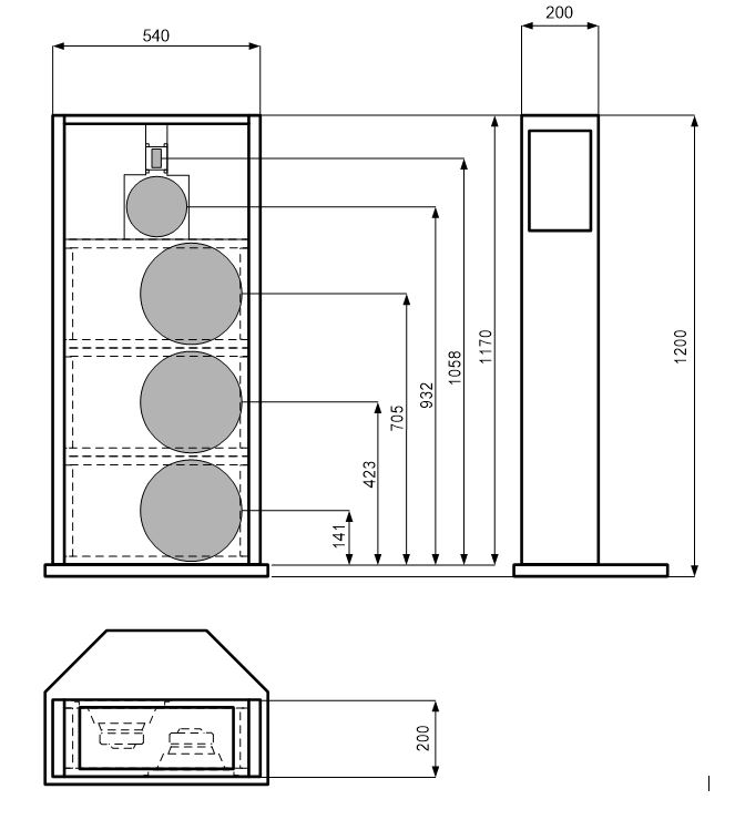
The construction of this cabinet can be made modular. Three separate woofer enclosures can be built and placed on each other. Side, front, top and bottom panels can be mounted against the woofer cabinets.
The midrange and the tweeter are mounted on a small baffle, placed flush with the woofer baffle. The space between this baffle and the side panels has to be left open to realize the dipole effect. Some holes are made in the top and side panels to minimize reflections of midrange and tweeter on the walls.
A passive crossover can be placed in the three woofer enclosures.
Dipole radiation behavior of the transducers in the cabinet
Some study has been done to investigate the dipole radiation behavior of the transducers in the cabinet. On and off axis SPL responses have been simulated and the polar diagram, the power response and the direcivity index are considered in detail.
For a good dipole behavior in the total frequency range, the polar diagram has to be uniform conform the dipole characteristics and the directivity index (DI) has to be about 4.7 dB and as flat as possible versus frequency.
To calculate the power response and directivity index, the horizontal and vertical SPL off axis responses of the woofer, the midrange and the tweeter are simulated in steps of 15 degrees, the speaker placed in a full sphere at 3m distance. The power is calculated out of the mean value of these curves. The power is represented as the SPL of an omnidirectional source at 3m distance in a full sphere with a SPL value equal to the power.
Woofer Dipole
For an improved SPL headroom, a 3 woofer array at the front and the back side are used. To limit the depth of the cabinet the woofers are placed asymmetric on the baffles. By placing the same woofer set at the front and the back side of the cabinet, the harmonic distortion is improved also.
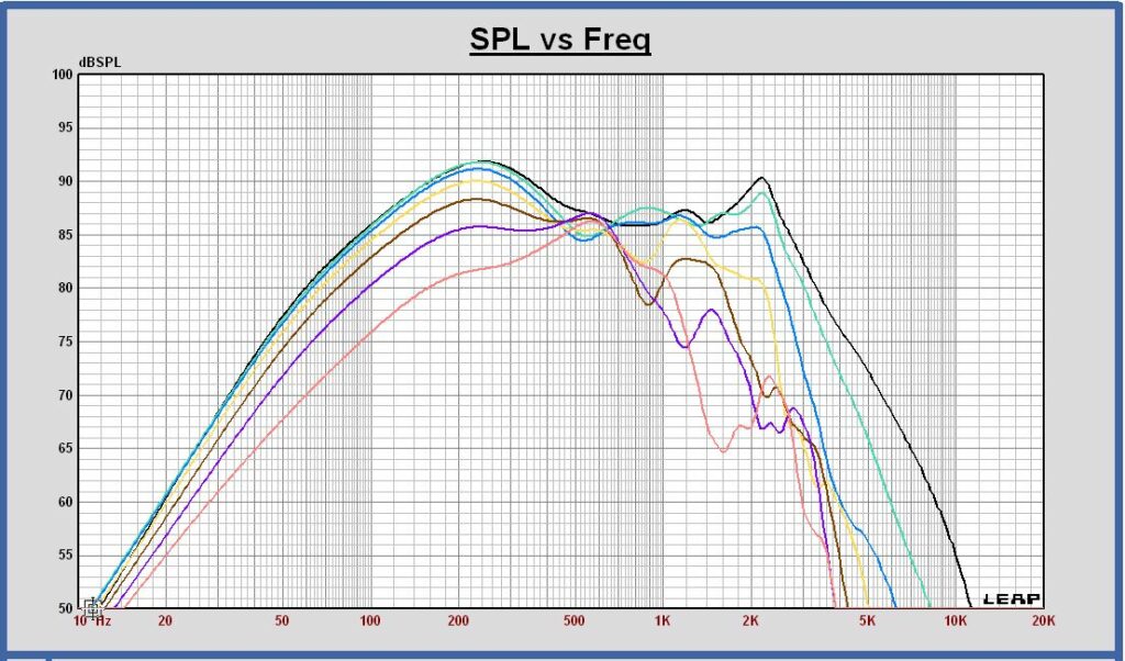
SPL on axis and horizontal off axis 15 30 45 60 75 90 degrees at 3m, 2.83 Vrms in full sphere
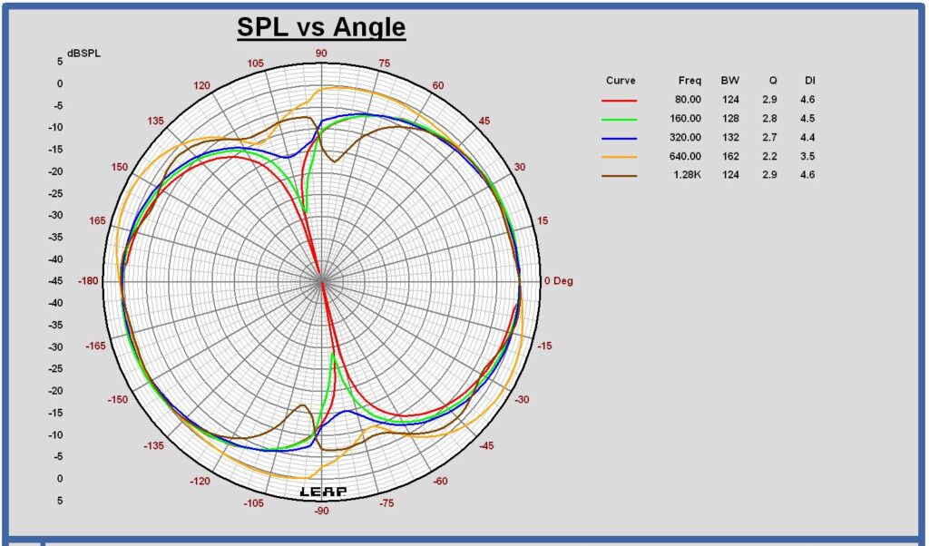
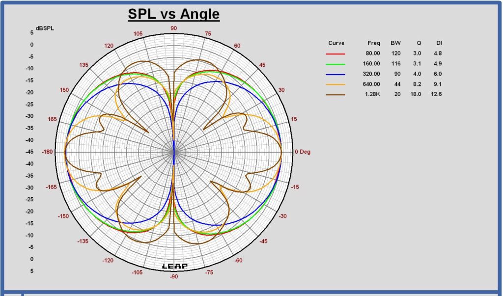
Horizontal polar diagram 80 – 160 – 320 – 640 – 1280 Hz at 3m in full sphere
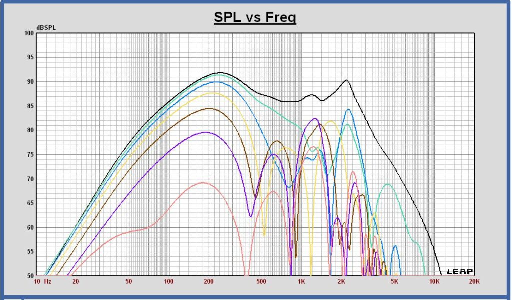
SPL on axis and vertical off axis 15 30 45 60 75 90 degrees at 3m, 2.83 Vrms in full sphere
Vertical polar diagram 80 – 160 – 320 – 640 – 1280 Hz at 3m in full sphere
SPL on axis and the power at 3m, 2.83 Vrms in full sphere

Directivity Index at 3m in full sphere

The DI decrease below 50 Hz is due to a simulation artifact. At low frequencies the DI is constant and equal to 4.7 dB.
- the woofer off axis SPL shows a good dipole behavior up to 300 Hz. The directivity index is about equal to the expected 4.7 dB of an ideal dipole.
- the horizontal polar diagram show a good dipole behavior up to 320 Hz. The litlle horizontal rotation of the polar diagram that can be observed is caused by the asymmetric position of the woofers on the baffle.
- in the vertical SPL off axis curves and also in the vertical polar polar diagram some dips appear above 400 Hz. The dips are caused by the 3 woofer vertical array. Up to 300 Hz, the vertical off axis behavior is still ok.
- as a conclusion of these simulations, this dipole woofer can be used up to 300 Hz in a 3 way system using high slope filtering for the crossover filter.
Midrange Dipole
To cover the frequency range of 300 to 3000 Hz, a 6.5 inch midwoofer is chosen.
For the best dipole behavior in the intended frequency range, the baffle width is chosen as small as possible. The transducer frame dimension is 18 cm, so the baffle width is chosen 19 cm.
SPL on axis and horizontal off axis 15 30 45 60 75 90 degrees at 3m, 2.83 Vrms in full sphere
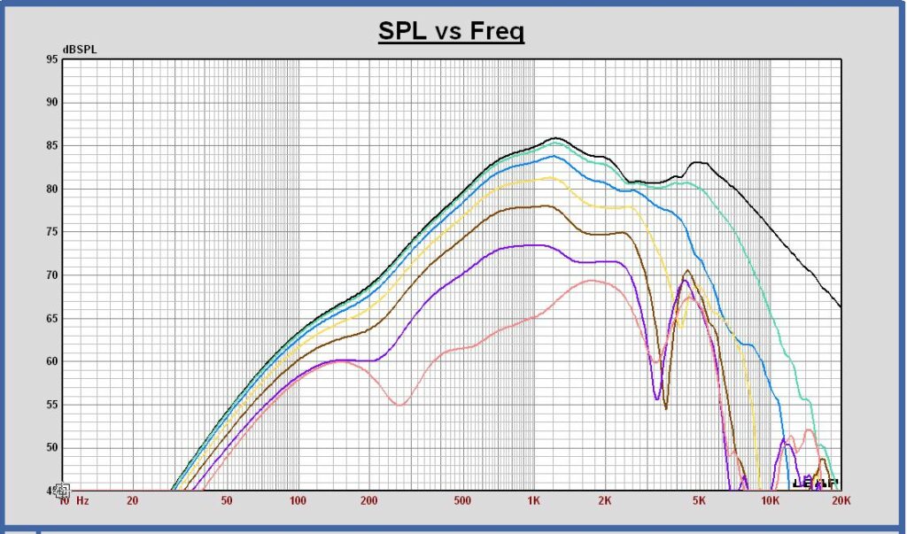
Horizontal polar diagram 160 – 320 – 640 – 1280 – 2560 Hz at 3m in full sphere

SPL on axis and vertical off axis 15 30 45 60 75 90 degrees at 3m, 2.83 Vrms in full sphere
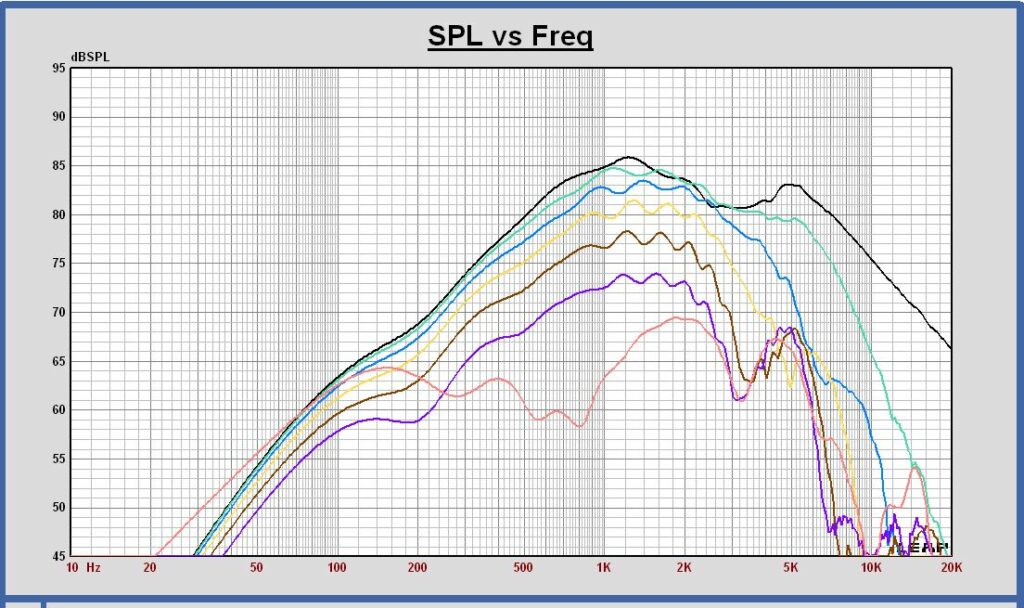
Vertical polar diagram 160 – 320 – 640 – 1280 – 2560 Hz at 3m in full sphere

SPL on axis and the power at 3m, 2.83 Vrms in full sphere
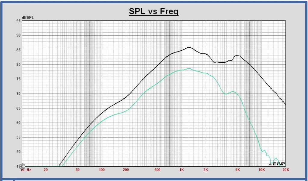
Directivity Index at 3m in full sphere
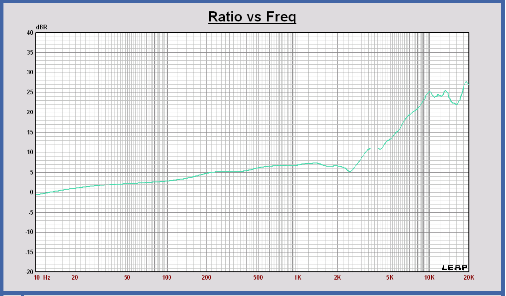
The DI decrease below 200 Hz is due to a simulation artifact. At low frequencies the DI is constant and equal to 4.7 dB.
- the midrange off axis SPL shows a good dipole behavior up to 2500 Hz.
- above 700 Hz the directivity index is higher than the expected 4.7 dB value of a dipole. It rises to 6 – 7 dB and is probably caused by the baffle width in that frequency range around 1 kHz. The DI value and the off axis behavior have to checked with SPL off axis measurements.
- the horizontal and vertical polar diagrams show a very good dipole behavior up to 2500 Hz.
- as a conclusion of these simulations, this dipole midrange can be used up to 2500 Hz in a 3 way system using high slope filtering for the crossover filter.
Tweeter Dipole
The Mundorf AMT17D2.2 dipole tweeter is chosen. It is a dipole design and is very small, interesting to realize a dipole effect as high frequent as possible. The outer flange dimensions of this tweeter are 60 x 60 mm. The tweeter baffle width is chosen also 60 mm.
SPL on axis and horizontal off axis 15 30 45 60 75 90 degrees at 3m, 2.83 Vrms in full sphere
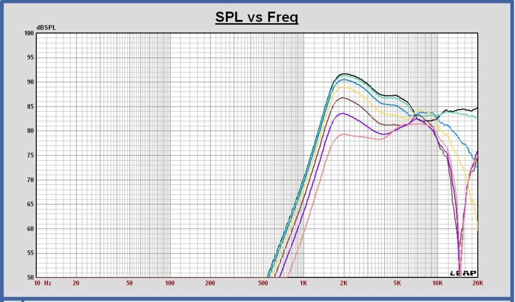
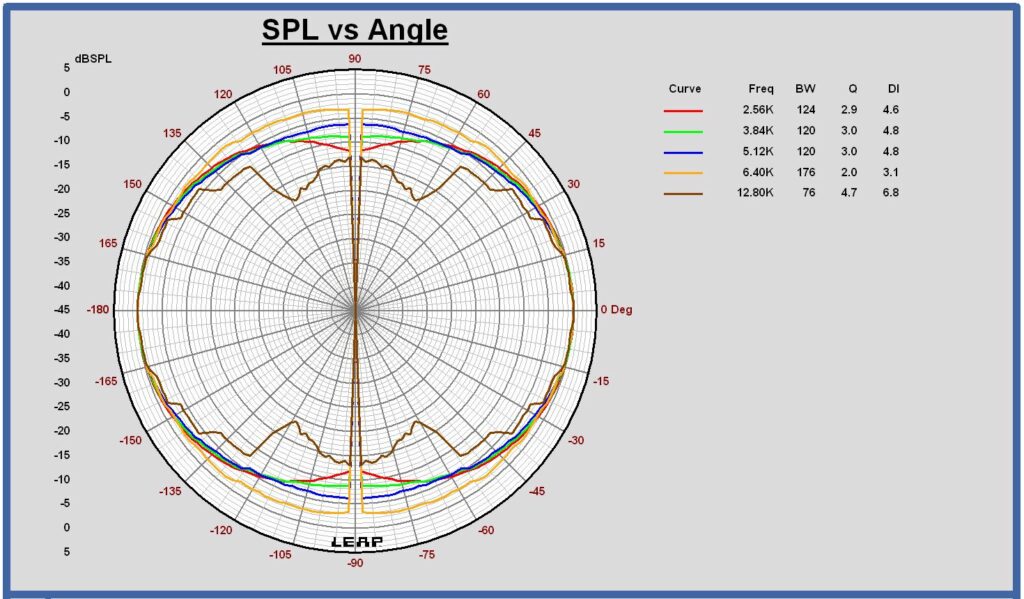
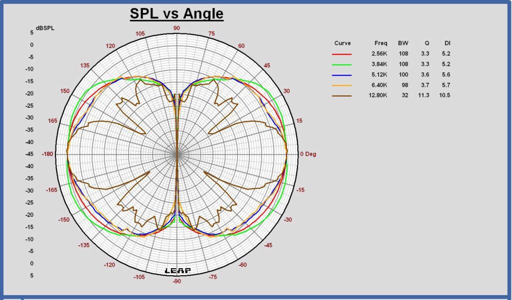
Horizontal polar diagram 2560 – 3840 – 5120 – 6400 – 12800 Hz at 3m in full sphere
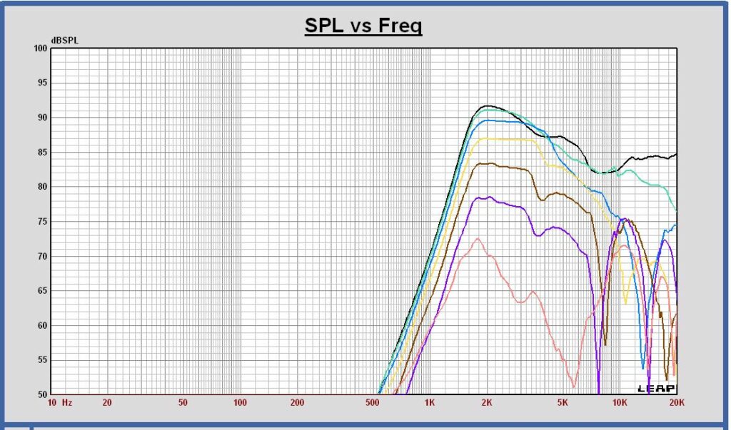
SPL on axis and vertical off axis 15 30 45 60 75 90 degrees at 3m, 2.83 Vrms in full sphere
Vertical polar diagram 2560 – 3840 – 5120 – 6400 – 12800 Hz at 3m in full sphere
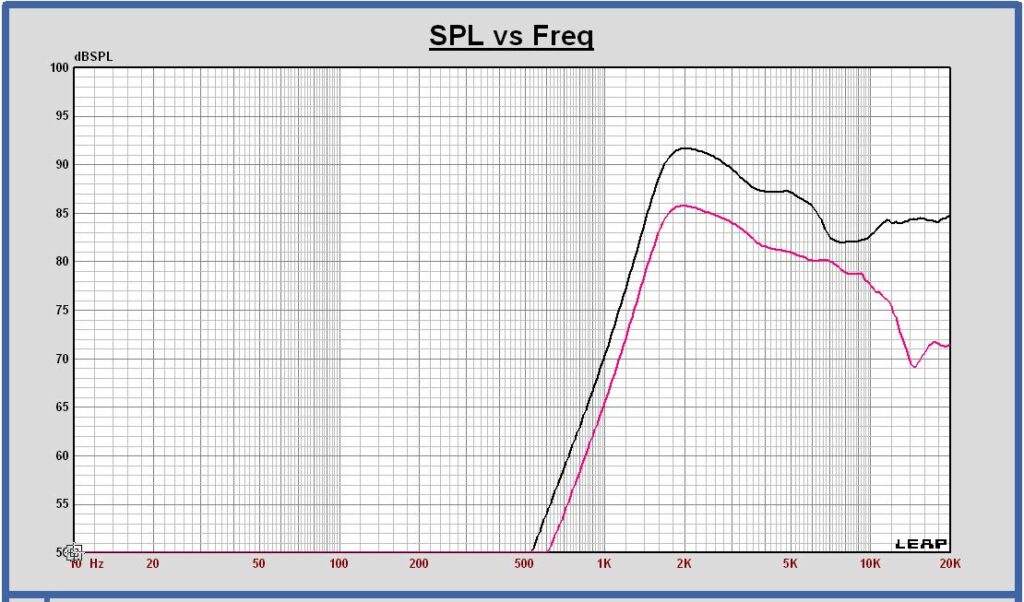
SPL on axis and the power at 3m, 2.83 Vrms in full sphere
Directivity Index at 3m in full sphere
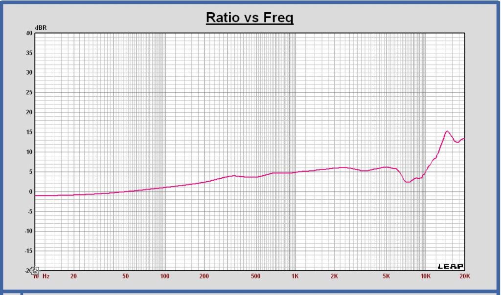
The DI decrease below 300 Hz is due to a simulation artifact. At low frequencies the DI is constant and equal to 4.7 dB.
- the tweeter off axis SPL shows a good dipole behavior up to 6500 Hz. Around 8 kHz the radiation becomes more omnidirectional. Off axis a SPL peak around 8 kHz appears.
- up to 6.5 kHz the directivity index becomes 5.5 dB, a little higher than the expected 4.7 dB value of a dipole. This rise is caused by the tweeter diaphragm heigth that is 50 mm. The DI value and the off axis behavior have to checked with SPL off axis measurements.
- the horizontal and vertical polar diagrams show a good dipole behavior up to 6500 Hz.
- as a conclusion of these simulations, this dipole midrange can be used up above 2500 – 3000 Hz in a 3 way system using high slope filtering for the crossover filter.
Crossover filter
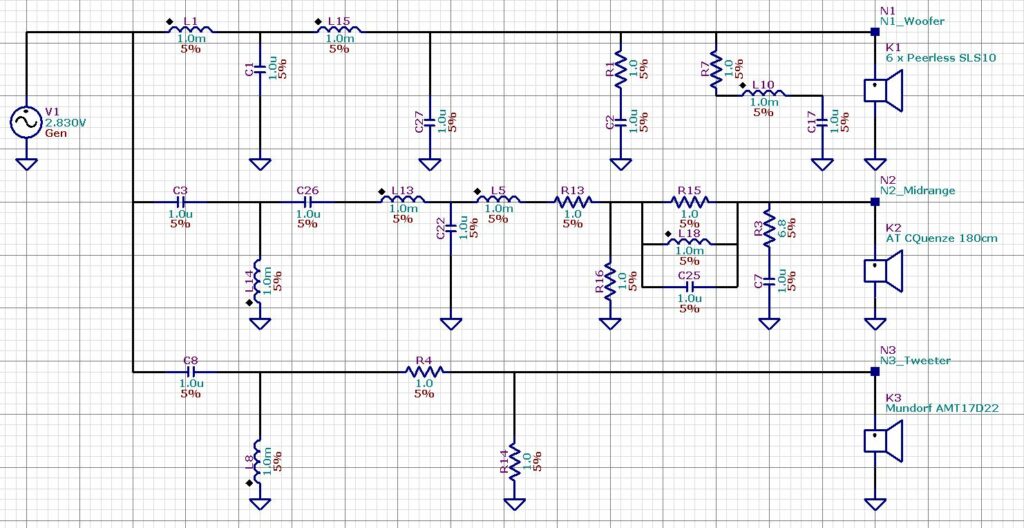
A Linkwitz-Riley 4th order crossover filter is designed. To realize flat curves for SPL, power and directivity index versus frequency, the crossover frequencies are chosen at 300 and 2700 Hz.
Crossover filter targets LR4 at 300 and 2700 Hz
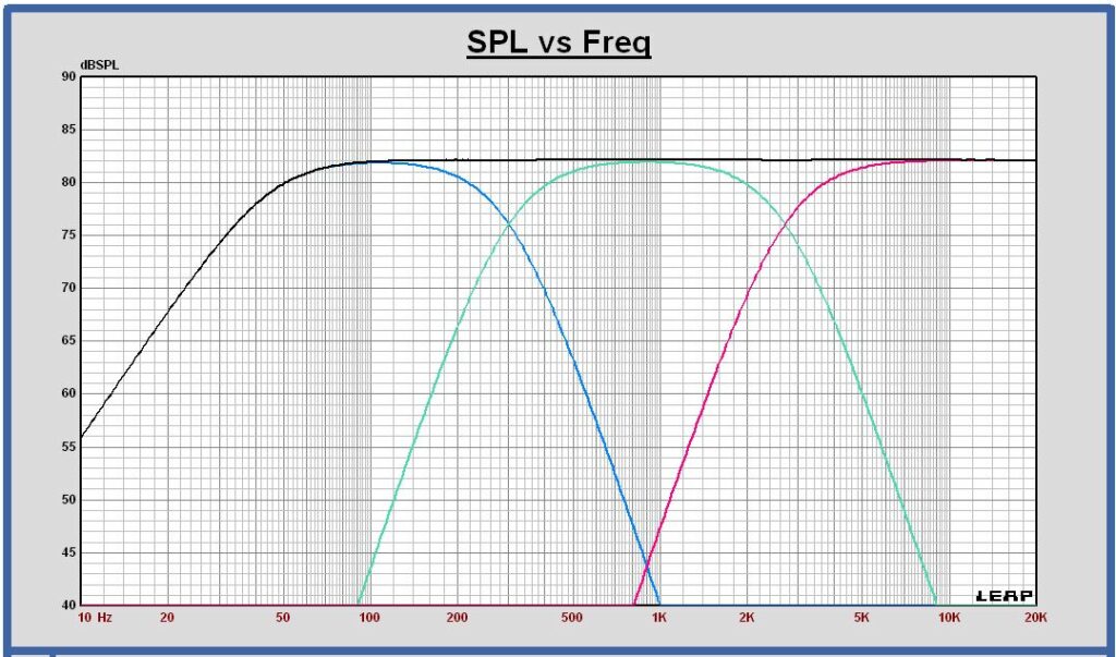
Crossover filter schematic configuration
SPL on axis of the filtered drivers and the sum at 1m, 2.83 Vrms

Impedance with crossover flter
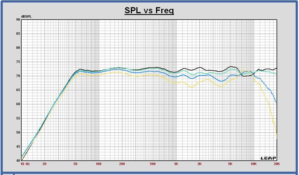
SPL horizontal off axis of the sum at 0 , 15, 30 and 45 degrees at 3m, 2.83 Vrms
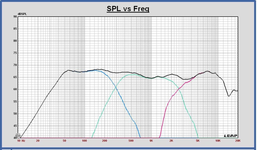
Power response of the filtered drivers and the sum in free space at 3m, 2.83 Vrms
Directivity Index in free space of the filtered drivers and the sum
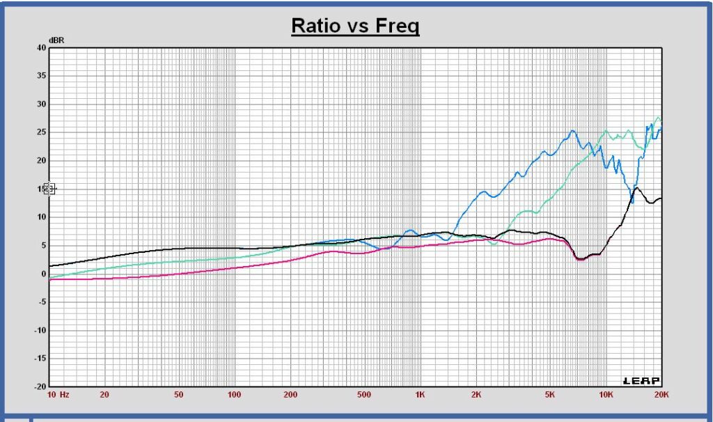
The total DI curve shows that this loudspeaker has a dipole radiation behavior up to 6 kHz. Around 8 kHz there is a DI dip due to a more omnidirectional behavior of the tweeter.
Maximum excursion and maximum SPL with the LR4 filter
Maximum excursion
With the designed Linkwitz – Riley 4th order filter, the woofer has a maximum excursion of 8.3 mm peak at 45 Hz for a voltage of 18.4 Vrms at the input of the filter.
The excursion of the midrange and the tweeter have been calculated also at 18.4 Vrms.
Excursion at 18.4 Vrms of woofer (blue), midrange (green) and tweeter (red)
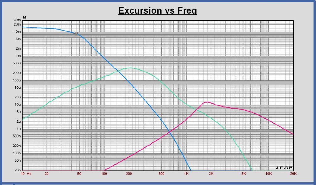
The midrange excursion is maximum at 211 Hz and equal to 0.338 mm peak.
The maximum specified linear excursion of the Audio Technology CQuenze 18 cm is 5.5 mm peak.
The tweeter excursion is maximum at 1680 Hz and equal to 0.013 mm peak.
The maximum linear excursion of the Mundorf AMT17D2.2 is not specified.
Maximum SPL
The maximum SPL for the operating frequency range 45 – 20000 Hz at maximum excursion of the woofer is 98 dB at 1m, 18.4 Vrms at the input of the crossover filter.
