
August 2026 High-performance constant-directivity all-Purifi loudspeaker concept
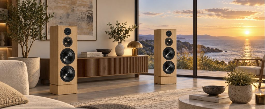
The VCL EX35 is a concept study — not yet prototype-validated — for a high-performance 3.5-way loudspeaker using Purifi drivers throughout.
The EX35 was conceived around four main design goals: tonal neutrality, controlled directivity and room power, extremely low distortion, and high dynamic capability. Purifi drivers were selected for their exceptionally smooth SPL response, with no significant resonances within their intended operating ranges, their extremely low distortion, and their wide dynamic range.
Design concept
- Compact high-output bass system using two 8″ active woofers and two 10″ passive radiators in a 60-litre enclosure.
- 1.5-way woofer configuration to control both the on-axis response and the transition of directivity and radiated room power towards the midrange.
- Directivity-matched transducer system, using the 1.5-way woofers, 5.25″ midrange and waveguide tweeter to achieve smooth directivity transitions through both crossover regions.
- Nearly constant directivity and uniform room power from approximately 300 Hz to 20 kHz, combined with very high dynamic headroom.
Two 8″ Purifi PTT8.0X04-NAB-01 woofers and two 10″ Purifi PTT10.0PR-NA2-01 passive radiators form the low-frequency system. The two active woofers operate together at low frequencies, while only the upper woofer remains active in the upper part of the woofer frequency range, creating the 1.5-way configuration.
This configuration is used not only to shape the on-axis frequency response, but also to control the loudspeaker’s directivity and radiated room power. Above approximately 300 Hz, the vertical directivity of the two woofers operating together starts to increase. Gradually removing the lower woofer from the response maintains wider radiation and provides a smoother transition in directivity and room power towards the midrange.
The new 5.25″ Purifi PTT5.25M08-NAA-05 is used as the midrange driver, while the Purifi PTT1.3T04-HAG-01 is used as the tweeter. The tweeter is particularly interesting from a directivity perspective. Thanks to its waveguide and coherer, it exhibits an almost constant directivity index from approximately 3 to 20 kHz on an infinite baffle.
When mounted in the EX35 cabinet, the interaction with the front baffle extends this controlled-directivity behaviour towards lower frequencies. Combined with the 5.25″ midrange and the 1.5-way dual-8″ woofer system, the complete loudspeaker is designed to achieve nearly constant directivity and uniform room power from approximately 300 Hz to 20 kHz.
The low-frequency system also provides very high headroom and exceptional output capability. With a representative music spectrum, the EX35 can reach a calculated maximum SPL of 117 dB at 1 m in full space, at the maximum permitted woofer excursion. This figure does not represent a flat 117 dB acoustic spectrum; the calculation takes into account the lower low-frequency energy of a representative music spectrum. The detailed excursion and maximum-SPL calculations are presented in Chapter 8.
Despite its low-frequency capability and dynamic headroom, the EX35 remains relatively compact. The cabinet dimensions are only W × H × D = 32 × 97 × 38 cm, including the crossover-filter compartment at the bottom.
A passive crossover network has been designed for the concept, using the 4-ohm versions of the woofers. An active crossover can optionally be designed to achieve the same target acoustic responses as the passive version.
The VCL EX35 is intended as a design study for experienced DIY builders and loudspeaker designers who value tonal neutrality, fine-detail resolution, controlled room interaction and dynamic realism — even at very high SPL levels.
The EX35 is currently a fully simulated concept design. Final crossover values, passive-radiator tuning and acoustic-centre offsets should be verified and fine-tuned through measurements of a physical prototype.
Contents
- Chapter 1 Specification Headlines
- Chapter 2 Speaker System
2.1 Woofer: 2 x Purifi PTT8.0X04 and 2 x Purifi PTT10.0PR
2.2 Midrange Purifi PTT5.25M08
2.3 Tweeter Purifi PTT1.3T04 - Chapter 3 Cabinet
- Chapter 4 On-axis responses of the transducers in the cabinet
- Chapter 5 Off axis responses, Polar diagrams, Power and Directivity Index of the transducers in the cabinet
5.1 Woofer: 2 x Purifi PTT8.0X04 and 2 x Purifi PTT10.0PR
5.2 Midrange Purifi PTT5.25M08
5.3 Tweeter Purifi PTT1.3T04 - Chapter 6 Crossover filter
- Chapter 7 Responses of the total speaker with crossover filter
- Chapter 8 Maximum excursion and maximum SPL with crossover filter
Chapter 1 Specification Headlines
- System: 3.5-way, passive radiator system, passive X-over
- Woofer: 2 x Purifi PTT8.0X04-NAB-01 and 2 x Purifi PTT10.0PR-NA2-01 for the passive radiator system
- Midrange: Purifi PTT5.25M08-NAA-05
- Tweeter: Purifi PTT1.3T04-HAG-01
- Low frequency response: F3 = 33 Hz
- Sensitivity: 84 dB at 1m, 2.83 Vrms, full space
- SPL at maximum excursion, 33 – 20000 Hz: 108 dB for a flat input spectrum and 117 dB for a music input spectrum, at 1m in full space
- Crossover: LR4 at 500 and 2500 Hz
- Impedance: value between 6 and 35 Ohm
- Cabinet dimensions, inclusive filter box: W x H x D = 32 cm x 97 cm x 38 cm
Chapter 2 Speaker System
Transducers
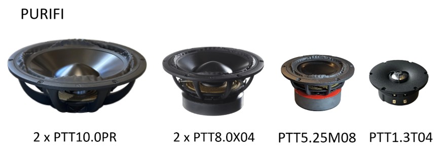
2.1 Woofer: 2 x Purifi PTT8.0X04 and 2 x Purifi PTT10.0PR
The Purifi PTT8.0X04 is an 8 inch woofer with an aluminum cone. Two pieces are used in a passive radiator system. The two woofers will be configured as a 1.5 way system.
This Purifi driver has a rather high cone mass of 48 gram; a small cabinet can be used to realize a low F3 value.
The 4 Ohm version of this woofer has been measured by HifiCompass, see following link.
Woofer Passive Radiator Loudspeaker System – Small Signal Analysis
Two 8″ Purifi woofers and two 10″ Purifi passive radiators are placed in a box of 60 L partially filled with wool. VCLLabs recommends long tail sheep wool as damping material. One box of 60 L or two separate boxes of 30 L can be used for the two woofers.
As a reference to calculate the responses of the passive radiator system, the article “Passive-Radiator Loudspeaker Systems” by Richard H.Small is used. In this post only the parameter values and the calculation results are summarized. For a more detailed understanding, the reference article can be used.
A passive radiator system using one woofer and one passive radiator in a cabinet with volume of 30 L is calculated. The response of two such passive radiators systems in a cabinet with double the volume of 60 L, has the same response at low frequencies for a series or parallel woofer configuration.
For one Purifi 8″ woofer: fs = 26 Hz; Vas = 70 L; Qts = 0.36. For the passive radiator: Sdp = 360 cm2;Vap = 82 L.
For a cabinet volume = 30 L, fp = 16 Hz (total cone mass for each passive radiator adjusted to 220 g), no cabinet filling and source resistance of 0 Ohm.
Then: Ts = 6.1 ms; Tp = 9.9 ms; alfa = 2.73; delta = 2.34; QT = 0.36
With the above parameter values, the frequency response on infinite baffle can be calculated, using the formula as mentioned in the reference article.
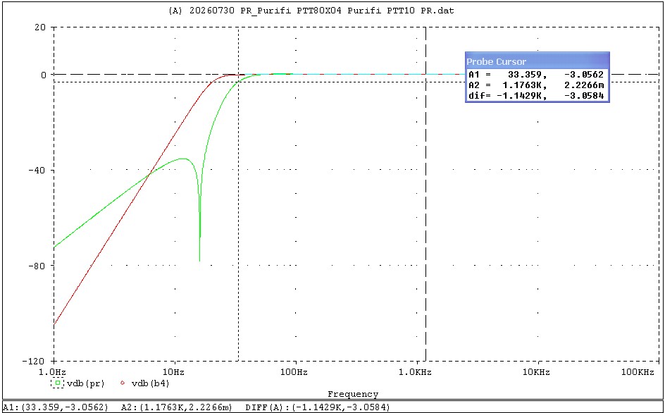
The green curve shows the passive radiator response, the red curve a Butterwoth B4 response at the same system frequency to compare with. F3 = 33 Hz with these parameter values.
This calculated response is a result with low losses, but the calculated response is very indicative.
Simulating the frequency response on infinite baffle in Leap with the same parameters for two woofers in series in a cabinet of 60 L, is shown in the next graph. The results are comparable. Some cabinet filling is applied in the Leap simulation.
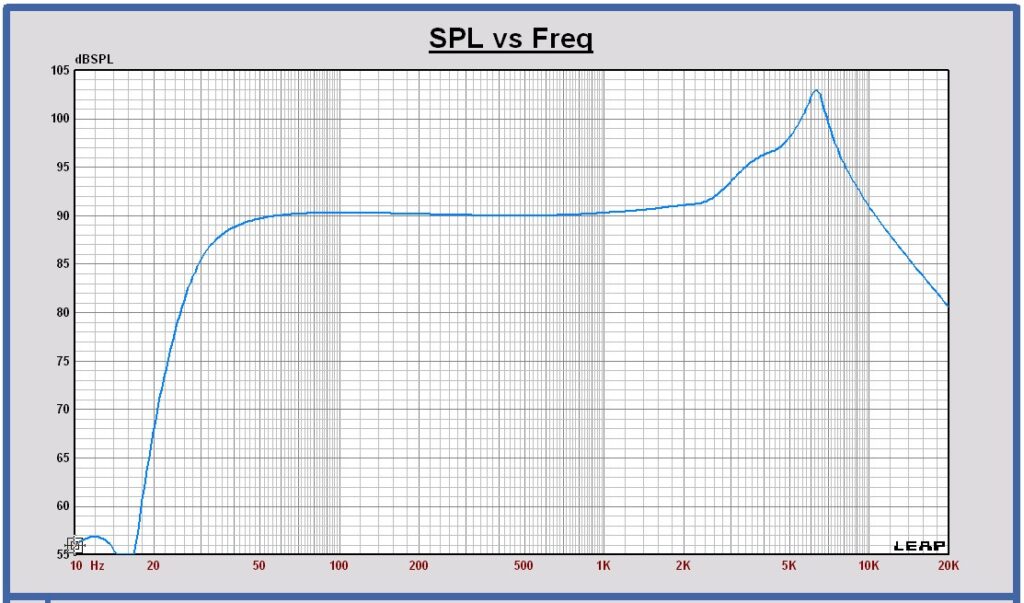
As a first conclusion of this passive radiator system study, the cabinet volume can be chosen 60 L for a two woofer system and the total mass of each passive radiator cone 220 gram. These values can be fine tuned with measurements.
2.2 Midrange: Purifi PTT5.25M08
The Purifi midrange PTT5.25M08 has an aluminum cone.
This midrange has been reviewed by HifiCompass, see following link.
Midrange – Small Signal Analysis
The 5.25 inch Purifi midrange is placed in a closed box of 4 L filled with sheep wool.
For this midrange: fs = 41 Hz; Vas = 9.1 L; Qts = 0.29 on infinite baffle.
Placed in the 4 L cabinet filled with wool: fc = 66 Hz and Qtc = 0.49.
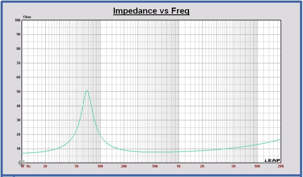
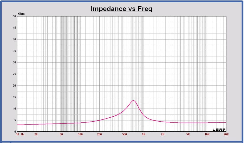
The amount of filling can be determined by measuring the maximum impedance of the transducer at the frequency fc. It has to be about 50 Ohm for Qtc to be 0.49. Then Qmc is around 3.66.
Impedance midrange PTT5.25M08-NAA-05 in the cabinet
2.3 Tweeter: Purifi PTT1.3T04
This tweeter has been reviewed by HifiCompass and it is performing very well, see following link.
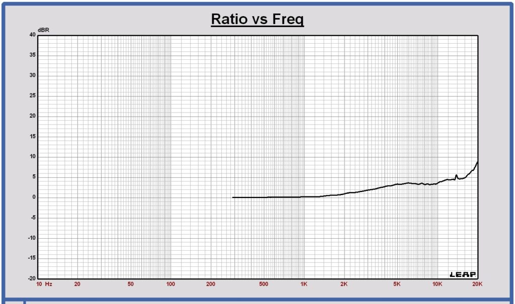
The tweeter has a waveguide. In the Purifi datasheet, the off-axis SPL responses on infinite baffle and the corresponding directivity index in a half space domain are published.
Horizontal SPL off axis response of tweeter Purifi PTT1.3T04
at 0, 15, 30, 45, 60, 75 and 85 degrees at 1m on infinite baffle (datasheet values)

Directivity Index DI of tweeter Purifi PTT1.3T04 on infinite baffle (datasheet values)
Chapter 3 Cabinet
Cabinet Mechanical drawing
These are the cabinet dimensions as used for this concept study.
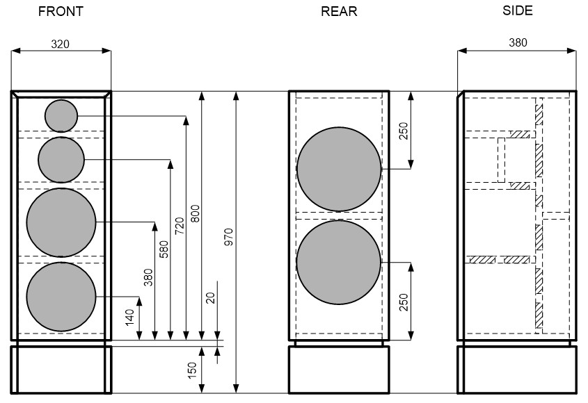
The speaker cabinet is standing on a box of 15 cm high, with an internal chamber to mount the crossover filter.
All panels are 22 mm thick.
The transducers are mounted flush with the front panel.
Chapter 4 On-axis responses of the transducers in the cabinet
4.1 SPL and impedance of the transducers in the cabinet
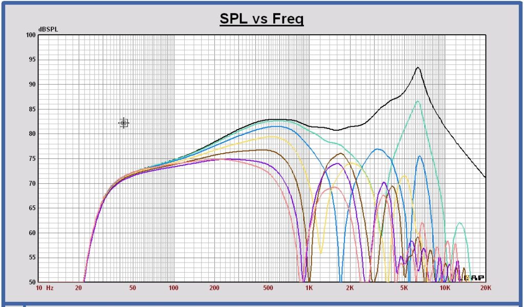
These are the SPL and impedance curves of the transducers placed in the cabinet in full space at 1 meter, 2.83 Vrms . The SPL responses on infinite baffle are also shown to see the impact of the cabinet on the response when placed in a full space domain.
SPL 2 x woofer Purifi PTT8.0X04 in series and 2 x Purifi PTT10.0PR in the cabinet in full space (blue curve) and on infinite baffle (pink curve)

The plot shows the SPL response of the two woofers connected in series. In the application the two woofers will be configured as a 1.5 way. Lower and upper woofer are operating together at low frequencies and the upper woofer only is active in the upper part of the woofer frequency band. In the off-axis analysis the upper woofer will be regarded separately to show the upper woofer individual directivity index response and compare it with the two woofers operating together.
Impedance 2x woofer Purifi PTT8.0X04 in series and 2 x Purifi PTT10.0PR in the 60 L cabinet

SPL midrange Purifi PTT5.25M08 in the cabinet in full space (green curve) and on infinite baffle (pink curve)

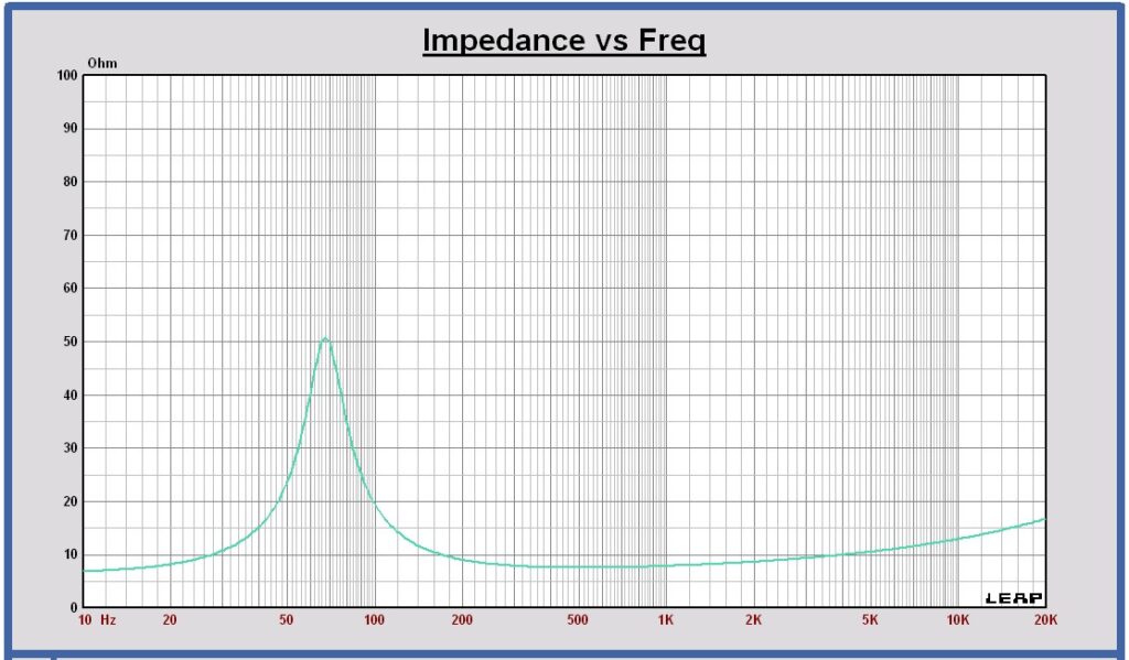
Impedance midrange Purifi PTT5.25M08 in the cabinet
SPL tweeter Purifi PTT1.3T04 in the cabinet in full space (red curve) and on infinite baffle (pink curve)

The on-axis tweeter shown, mounted in the cabinet in full space is simulated in the Leap tool using an approximation. The published on axis response on infinite baffle of the datasheet can be used in this approximation. It is explained in chapter 5.3.
Impedance tweeter Purifi PTT1.3T04 in the cabinet
5 Off-axis responses, Polar diagrams, Power and Directivity Index of the transducers in the cabinet
To calculate the power response and directivity index, the horizontal and vertical SPL off axis responses of the woofer, midrange and the tweeter are simulated in steps of 15 degrees, the speaker placed in full space at 3m distance. The power is calculated out of the mean value of these curves. The power is represented as the SPL of an omnidirectional source at 3m distance in full space with a SPL value equal to the power.
5.1 Woofer 2 x Purifi PTT8.0X04 in series and 2 x Purifi PTT10.0PR
As the two woofers will be configured as a 1.5 way in this application, the off axis study is done for the two woofers connected in series and also for the upper woofer operating only. In this way the differences of the off axis, power and directivity index responses can be observed, for both woofers and the upper woofer operating.
Two woofers operational
Horizontal SPL off axis response of 2 x woofer Purifi PTT8.0X04 in series and 2 x Purifi PTT10.0PR in the cabinet
at 0, 15, 30, 45, 60, 75 and 90 degrees at 3m, 2.83Vrms in full space

Vertical SPL off axis response of 2 x woofer Purifi PTT8.0X04 in series and 2 x Purifi PTT10.0PR in the cabinet
at 0, 15, 30, 45, 60, 75 and 90 degrees at 3m, 2.83Vrms in full space
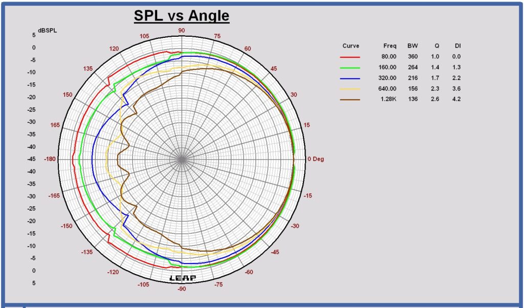
Horizontal polar diagram 2 x woofer Purifi PTT8.0X04 in series and 2 x Purifi PTT10.0PR in cabinet in full space
at 80 – 160 – 320 – 640 – 1280 Hz
Vertical polar diagram 2 x woofer Purifi PTT8.0X04 in series and 2 x Purifi PTT10.0PR in cabinet in full space
at 80 – 160 – 320 – 640 – 1280 Hz

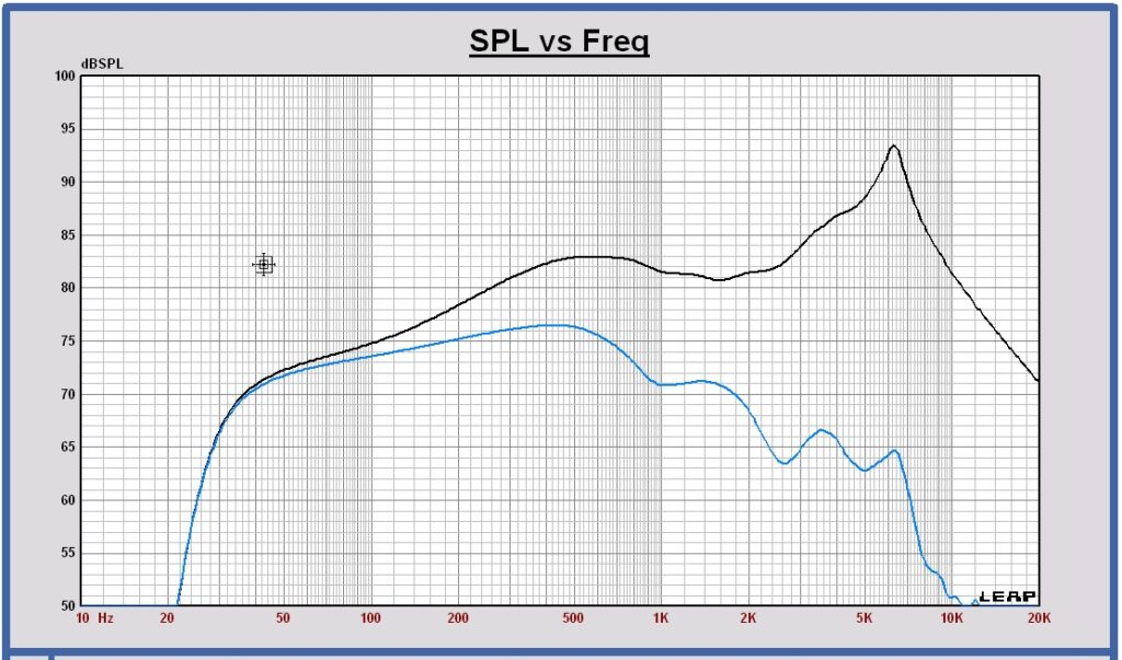
SPL on axis (black) and Power (blue) of 2 x woofer Purifi PTT8.0X04 in series and 2 x Purifi PTT10.0PR in the cabinet at 3m, 2.83 Vrms in full space
Directivity Index DI in full space of 2 x woofer Purifi PTT8.0X04 in series and 2 x Purifi PTT10.0PR in the cabinet at 3m in full space

Back to top of page
Only upper woofer operational
Horizontal SPL off axis response of upper woofer Purifi PTT8.0X04 and upper Purifi PTT10.0PR in the cabinet
at 0, 15, 30, 45, 60, 75 and 90 degrees at 3m, 2.83 Vrms in full space
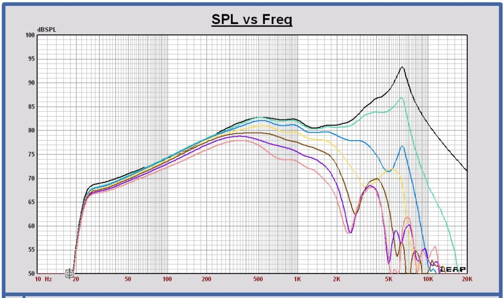
Vertical SPL off axis response of upper woofer Purifi PTT8.0X04 and upper Purifi PTT10.0PR in the cabinet
at 0, 15, 30, 45, 60, 75 and 90 degrees at 3m, 2.83 Vrms in full space
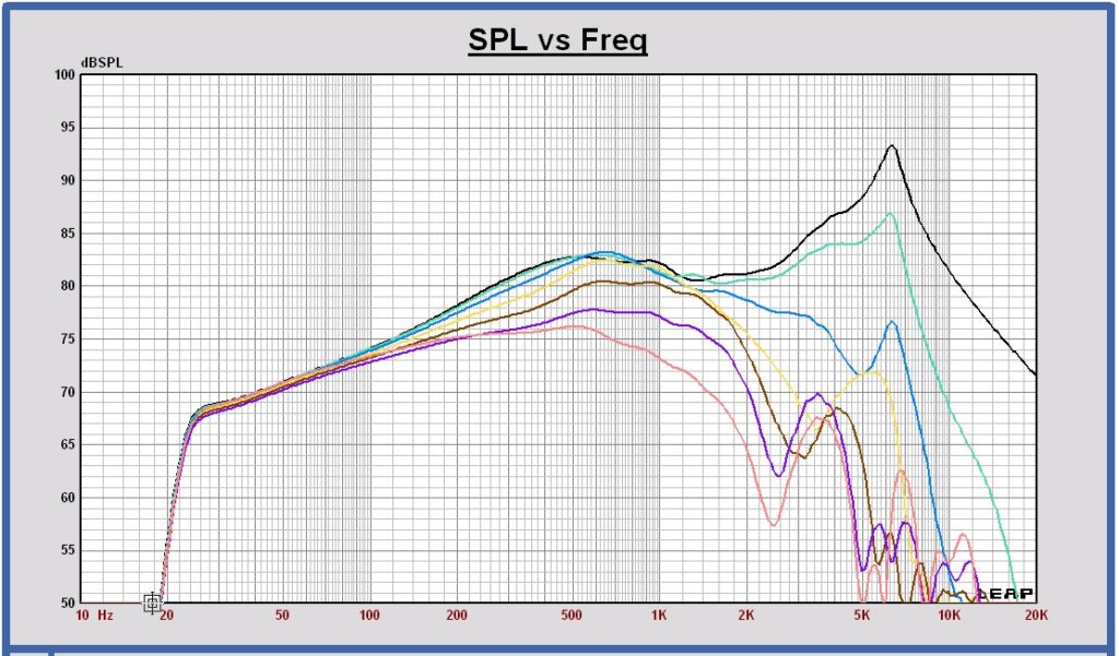
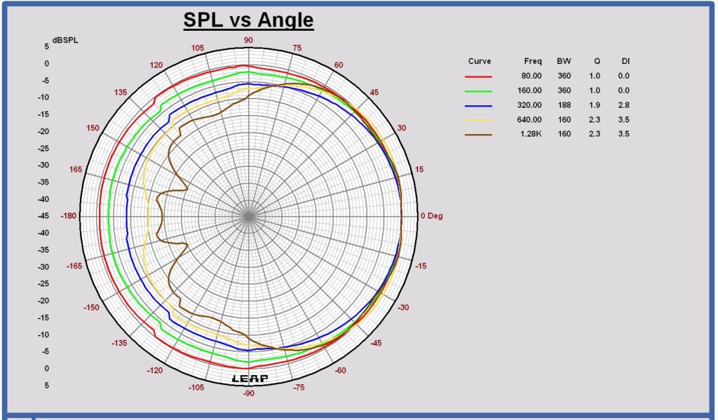
Horizontal polar diagram upper woofer Purifi PTT8.0X04 and upper Purifi PTT10.0PR in cabinet in full space
at 80 – 160 – 320 – 640 – 1280 Hz

Vertical polar diagram upper woofer Purifi PTT8.0X04 and upper Purifi PTT10.0PR in cabinet in full space
at 80 – 160 – 320 – 640 – 1280 Hz
SPL on axis (black) and Power (blue) of upper woofer Purifi PTT8.0X04 and upper Purifi PTT10.0PR in the cabinet at 3m, 2.83 Vrms in full space

Directivity Index DI of upper woofer Purifi PTT8.0X04 and upper Purifi PTT10.0PR in the cabinet at 3m in full space
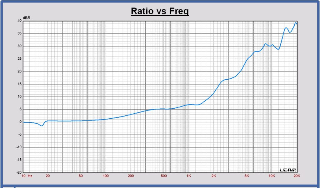
Directivity Index Comparison – Two woofers and only upper woofer operational
Directivity Index of two woofers operational (dark blue) and only upper woofer operational (ligth blue) in the cabinet in full space
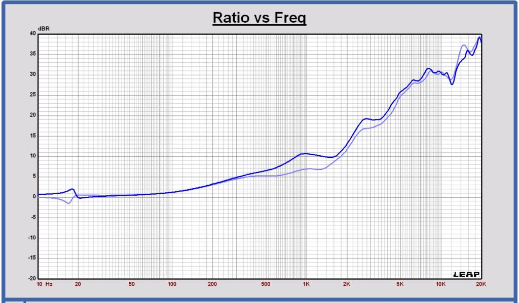
Above 300 Hz, two woofers will have a higher directivity than one woofer, because the vertical beaming of two woofers starts at a lower frequency. It means that above 300 Hz, the radiated room power of two woofers operating together becomes lower. The 1.5 way can be configured that only the upper woofer becomes active above 300 Hz to make the radiated power of the woofer system higher above 300 Hz.
5.2 Midrange Purifi PTT5.25M08
Horizontal SPL off axis response of midrange Purifi PTT5.25M08 in the cabinet
at 0, 15, 30, 45, 60, 75 and 90 degrees at 3m, 2.83 Vrms in full space

Vertical SPL off axis response of midrange Purifi PTT5.25M08 in the cabinet
at 0, 15, 30, 45, 60, 75 and 90 degrees at 3m, 2.83 Vrms in full space

Horizontal polar diagram midrange Purifi PTT5.25M08 in cabinet in full space at 320 – 640 – 1280 – 2560 – 3840 Hz
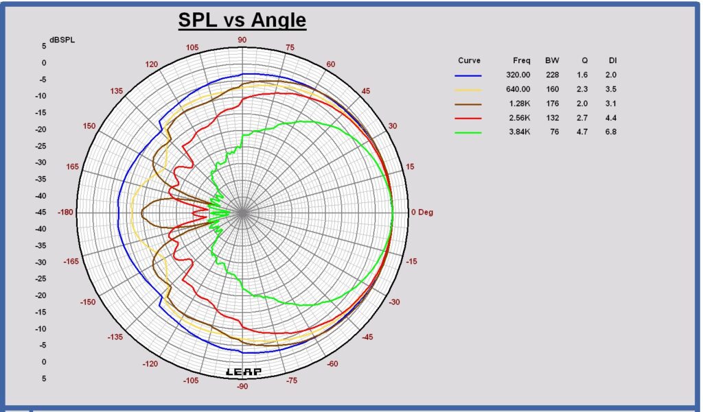
Vertical polar diagram midrange Purifi PTT5.25M08 in cabinet in full space at 320 – 640 – 1280 – 2560 – 3840 Hz

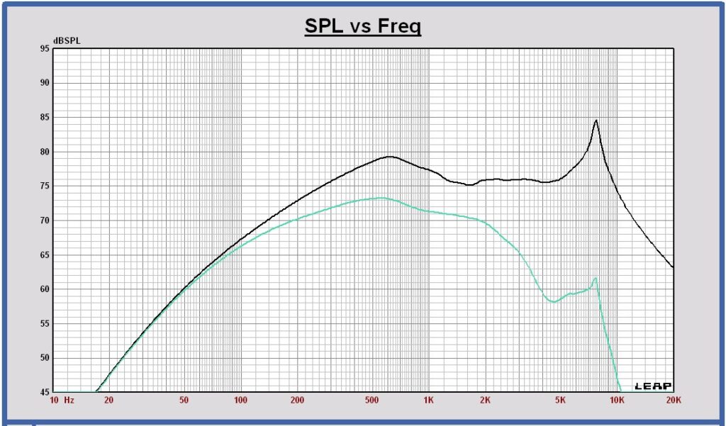
SPL on axis (black) and Power (green) of midrange Purifi PTT5.25M08 in the cabinet at 3m, 2.83 Vrms in full space
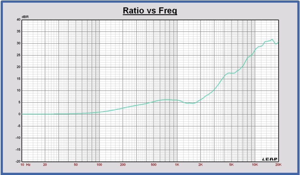
Directivity Index DI of midrange Purifi PTT5.25M08 at 3m in full space
5.3 Tweeter Purifi PTT1.3T04
Approximation used for the off-axis simulations in Leap
In the application, the tweeter is mounted in a cabinet in a full-space domain. The off-axis SPL responses will therefore be different from the off-axis responses published in the datasheet. As we do not have the tweeter and the cabinet available yet, we are not able to measure the off-axis responses with the tweeter mounted in the cabinet. Such measurements would be the most straightforward way to obtain these responses.
At this stage, we will therefore use an approximation for the off-axis simulations in LEAP. It is not possible to create a waveguide model in LEAP. We will use a tweeter model with the same TSP as the Purifi tweeter, flush-mounted on the cabinet front panel, without a waveguide.
The approximation consists of the following steps:
The horizontal off-axis responses of the waveguide tweeter on an infinite baffle, as published in the datasheet, will then be multiplied by the corresponding (k(\theta,f)) ratios. In this way, we obtain an approximation of the horizontal off-axis responses of the tweeter with waveguide, mounted in the cabinet and placed in a full-space domain.
The horizontal off-axis responses of this tweeter model, mounted on an infinite baffle, will be simulated at 15°, 30°, 45°, 60°, 75° and 85° horizontal off-axis.
The horizontal off-axis responses of the same tweeter model, mounted in the cabinet and placed in a full-space domain, will be simulated at the same angles: 15°, 30°, 45°, 60°, 75° and 85° horizontal off-axis.
At each angle, the ratio k(θ,f) between the simulated response of the tweeter mounted in the cabinet in full space and the response of the same tweeter mounted on an infinite baffle will be calculated. These ratios represent the angle-dependent cabinet diffraction transfer functions: k(15,f); k(30,f);…; k(85,f)
The remaining approximation is that the cabinet diffraction transfer function is assumed to depend primarily on the angular radiation of the source and not on the detailed aperture field of the waveguide. This approximation is expected to introduce only small errors, except at the highest frequencies, where the waveguide aperture becomes relatively large compared with the acoustic wavelength.
Horizontal SPL off axis response of tweeter Purifi PTT1.3T04-HAG-01 in the cabinet
at 0, 15, 30, 45, 60, 75 and 90 degrees at 3m, 2.83 Vrms in full space
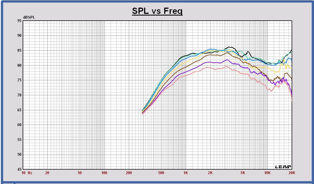
Vertical SPL off axis response of tweeter Purifi PTT1.3T04-HAG-01 in the cabinet
at 0, 15, 30, 45, 60, 75 and 90 degrees at 3m in full space
This response has not yet been simulated.
Horizontal polar diagram tweeter Purifi PTT1.3T04-HAG-01 in full space at 1.2 – 2.5 – 3.8 – 5.1 – 6.4 – 12.8 kHz
This response has not yet been simulated.
Vertical polar diagram tweeter Purifi PTT1.3T04-HAG-01 in cabinet in full space at 1.2 – 2.5 – 3.8 – 5.1 – 6.4 – 12.8 kHz
This response has not yet been simulated.
SPL on axis (black) and Power (red) of tweeter Purifi PTT1.3T04-HAG-01 in the cabinet at 3m, 2.83 Vrms in a single hemisphere
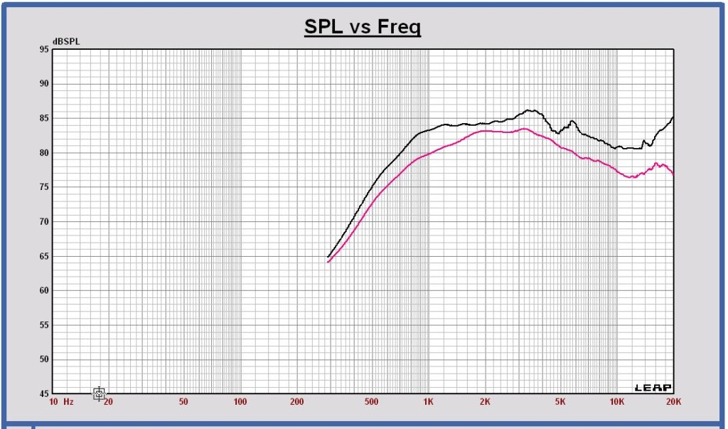
Directivity Index DI of tweeter PTT1.3T04-HAG-01 in the cabinet at 3m in a single hemisphere

The directivity index of the tweeter in the cabinet is calculated in the frontal single hemisphere and not in full space, as there are no SPL off-axis 90 to 180 degrees available on an infinite baffle as this is not relevant.
In order to compare this tweeter directivity in a single hemisphere with the other drivers in this speaker application, the woofer and midrange directivity indexes will be considered also in a frontal single hemisphere, see chapter 6.
Chapter 6 Crossover Filter
All responses without crossover filter
SPL of lower woofer and upper woofer (blue), midrange (green), tweeter (red); transducers placed in the cabinet, on-axis at 1 meter, 2.83 Vrms in full space

Directivity Index of upper woofer (brown), midrange (green), tweeter (red); transducers placed in the cabinet in the frontal single hemispere
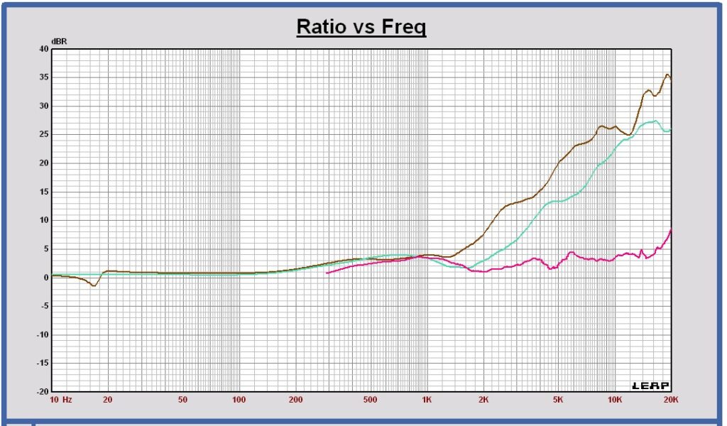
In order to keep the DI of the sum response flat, this directivity index plot shows that the crossover frequencies can be chosen at 500 and 2500 Hz.
Filter Targets
LR4 at 500 and 2500 Hz

Sensitivity is 84 dB. The -3 dB cutoff frequency (F3) is 33 Hz.
As the woofer system is a 1.5 way, the lower and upper woofer have different targets. The lower woofer target is shown in yellow and the upper woofer target is shown in brown color. The sum of the lower and upper woofer targets is shown in blue color and it represents the total woofer target.
Acoustic centers of the transducers
For this concept design, the acoustic center of the woofer is assumed to be 10 mm behind the acoustic center of the midrange and 20 mm behind the acoustic center of the tweeter.
Schematic configuraton
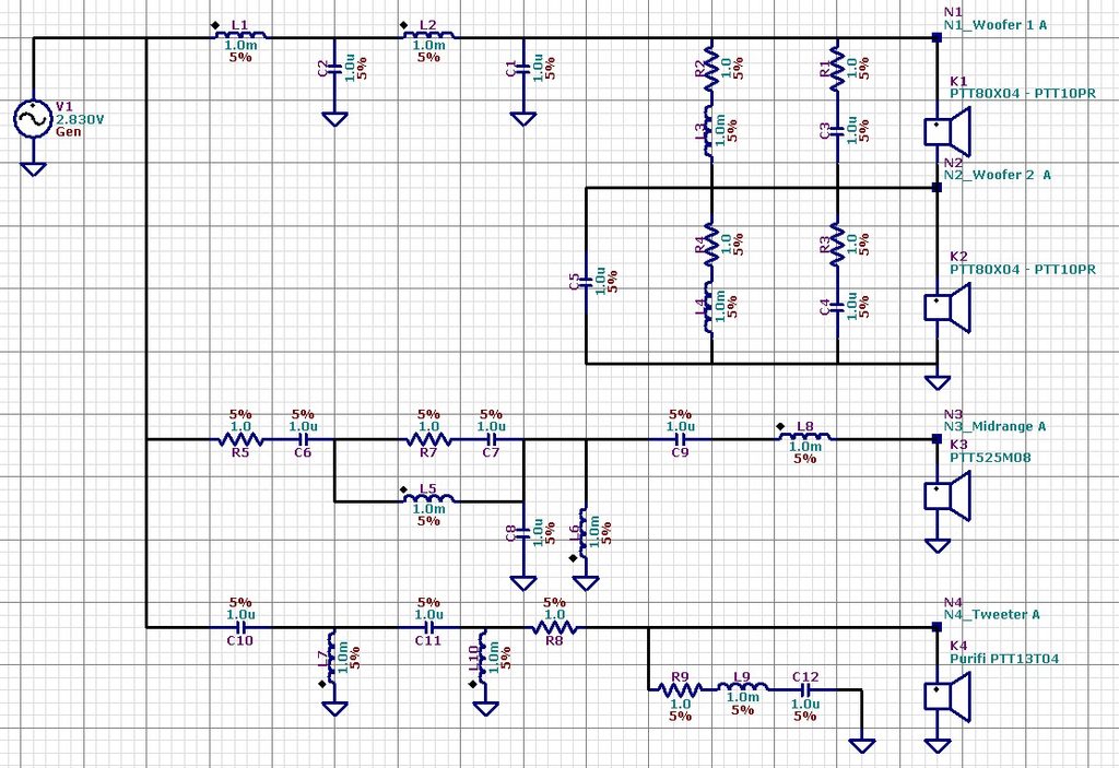
Filter components
For a good quality crossover, air core wire coils, MKP capacitors and 10W MOX or carbon resistors, are recommended.
Chapter 7 Responses of the total speaker with crossover filter
SPL of the filtered drivers and the sum at 1m, 2.83 Vrms, full space

SPL of lower woofer in yellow, SPL upper woofer in brown, SPL midrange in green and SPL tweeter in red
Impedance

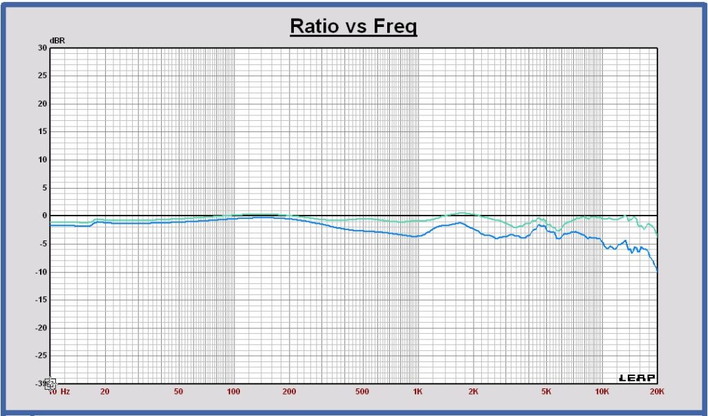
SPL of the sum off axis at 3m, 2.83 Vrms, in full space, normalized to the on-axis sum response
30 degrees in green, 60 degrees in blue
Directivity Index in the single frontal hemisphere of the filtered drivers and the sum
upper woofer in brown, midrange in green, tweeter in red and sum in black

Chapter 8 Maximum excursion and maximum SPL with crossover filter
Maximum excursion
With the designed Linkwitz – Riley 4th order filter, each woofer has a maximum excursion of 9.3 mm peak at 45 Hz for a voltage of 78 Vrms at the input of the filter. It means that this passive radiator system using two active 8″ woofers and two 10″ passive radiators has a lot of headroom.
The peak excursion of the midrange and the tweeter have been calculated also at 78 Vrms.
Excursion peak at 78 Vrms of upper woofer (brown), upper passive radiator (yellow), midrange (green) and tweeter (red)

Each passive radiator excursion is maximum at 21 Hz and equal to 15.4 mm peak.
The maximum specified linear excursion of the Purifi PTT10.0PR is 25 mm peak.
The midrange excursion is maximum at 426 Hz and equal to 0.278 mm peak.
The maximum specified linear excursion of the Purifi PTT5.25M08 is 2.9 mm peak.
The tweeter excursion is maximum at 2460 Hz and equal to 0.113 mm peak.
The maximum linear excursion of the Purifi PTT1.3T04 is 0.5 mm peak.
Maximum SPL
For a flat frequency spectrum at the input:
at maximum excursion of the woofer at 45 Hz, the maximum SPL for the operating frequency range 33 – 20000 Hz is 108 dB, at 1m and 78 Vrms at the input of the crossover filter.
For a mean music frequency spectrum at the input:
at maximum excursion of the woofer at 45 Hz, the maximum SPL for the operating frequency range 33 – 20000 Hz is 117 dB, at 1m and 78 Vrms @ 45 Hz at the input of the crossover filter.
The 117 dB figure does not represent a flat 117 dB acoustic spectrum. It is calculated using a representative music spectral distribution, in which substantially less energy is present at low frequencies than for a flat-spectrum test signal.
